VLT
®
5000 Series
Programming
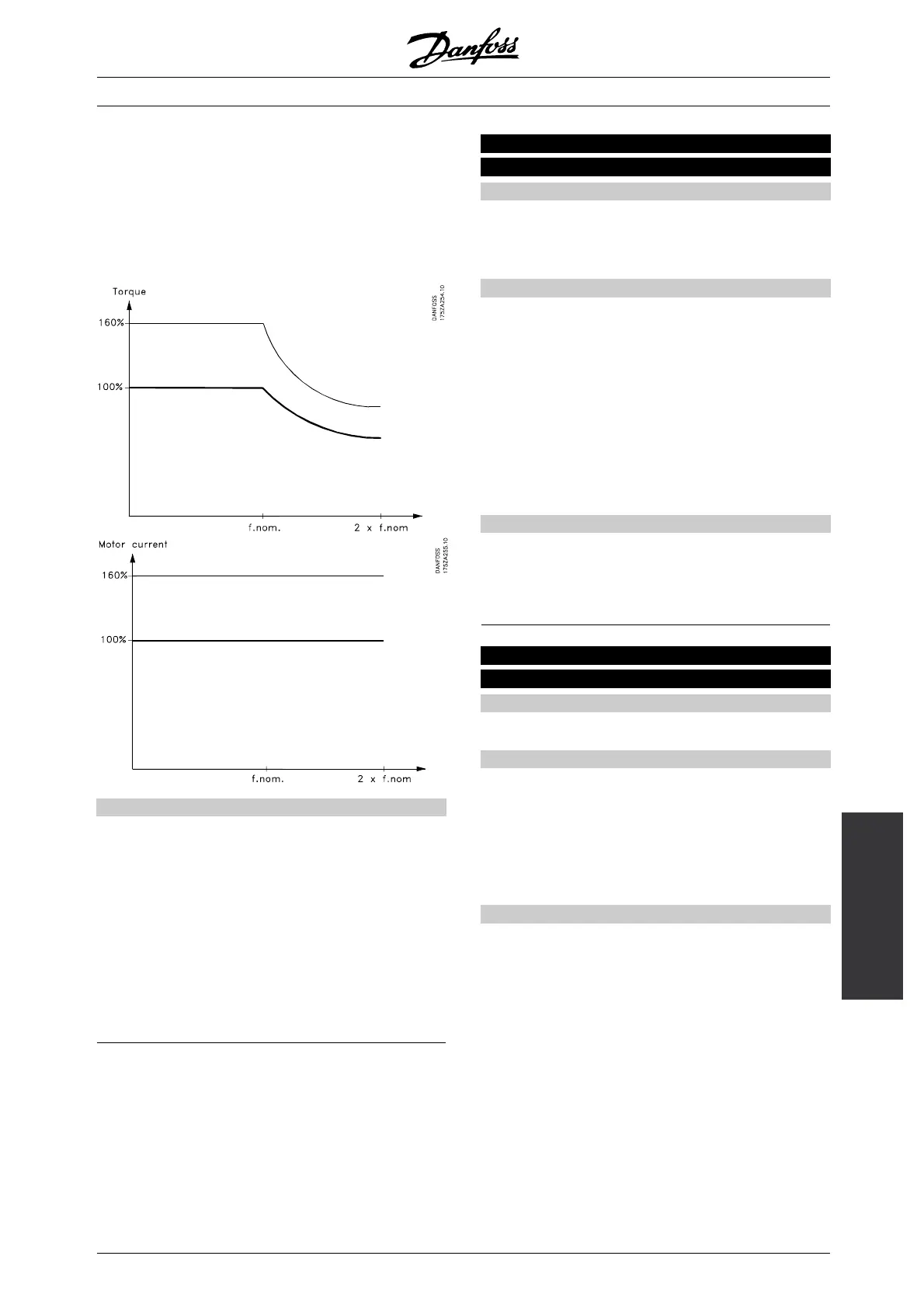
This is where to set the torque limit for motor operation.
Thetorquelimiterisactiveinthefrequencyrangeup
to the rated motor frequency (parameter 104).
In the oversynchronous range, where the frequency
is higher than the rated motor frequency, this
function acts as a current limiter.
See fig. below.
Description of choice:
See also parameter 409 for further details.
In order to protect the motor from reaching pull-out
torque, the factory setting is 1.6 x the rated
motor torque (calculated value).
If a synchronous motor is used, the torque limit must
be increased in relation to the factory setting.
If a setting in parameters 101-106 is changed,
parameters 221/222 are not automatically
reversed to the factory setting.
222 Torque limit for generating operation
(TORQ LIMIT GENER)
Value:
0.0 % - xxx.x % of T
M,N
✭ 160 %
The max. torque depends on the unit and
the motor size selected.
Function:
This function is relevant for all application
configurations; speed, process and torque control.
This is where to set the torque limit for generating
operation. The torque limiter is active in the frequency
range up to the rated motor frequency (parameter 104).
In the oversynchronous range, where the frequency
is higher than the rated motor frequency, this
function acts as a current limiter.
See fig. for parameter 221 as well as parameter
409 for further details.
Description of choice:
If Resistor brake [1] has been selected in
parameter 400, the torque limit is changed to
1.6 x the rated motor torque.
223 Warning: Low current
(WARN. CURRENT LO)
Value:
0.0 - parameter 224
✭ 0.2 A
Function:
When the motor current is below the limit,
I
LOW
, programmed in this parameter, the display
indicates CURRENT LOW.
The signal outputs can be programmed to transmit a
status signal via terminal 42 or 45 as well as via relay
output 01 or 04 (parameter 319, 321, 323 or 326).
Description of choice:
The lower signal limit I
LOW
of the motor current
must be programmed within the normal working
range of the frequency converter.
✭
= factory setting. () = display text [] = value for use in communication via serial communication port
MG.51.A9.02 - VLT is a registered Danfoss trademark
119
 Loading...


