3-77 Ramp 4 S-ramp Ratio at Decel. Start
Range: Function:
50 %* [Application dependant] Enter the proportion of the total ramp-down time (par. 3-72
Ramp 4 Ramp Down Time
) where the
deceleration torque increases. The larger the percentage value, the greater the jerk compensation
achieved, and thus the lower the torque jerks in the application.
3-78 Ramp 4 S-ramp Ratio at Decel. End
Range: Function:
50 %* [Application dependant] Enter the proportion of the total ramp-down time (par. 3-72
Ramp 4 Ramp Down Time
) where the
deceleration torque decreases. The larger the percentage value, the greater the jerk compensation
achieved, and thus the lower the torque jerks in the application.
3.5.8 3-8* Other Ramps
Configure parameters for special ramps e.g. Jog or Quick Stop.
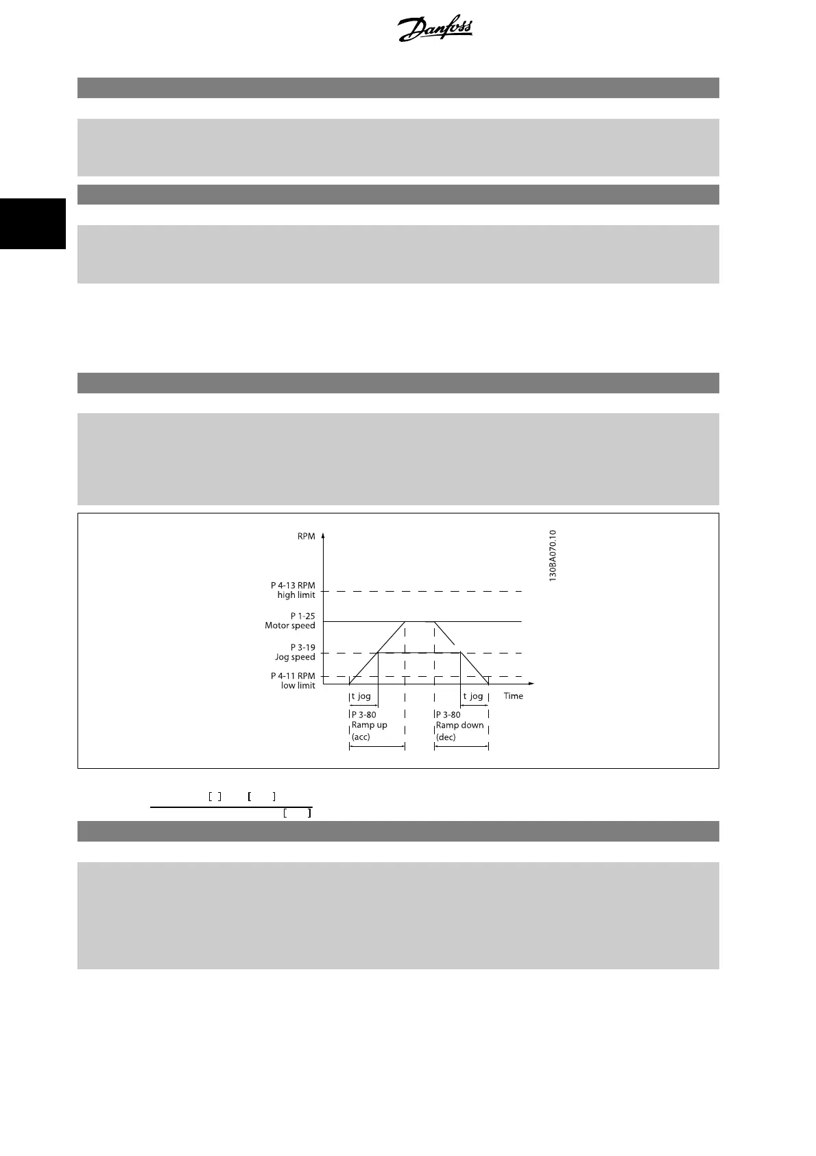
3-80 Jog Ramp Time
Range: Function:
Application
dependent*
[0.01 - 3600.00 s] Enter the jog ramp time, i.e. the acceleration/deceleration time between 0 RPM and the rated motor
frequency n
s
. Ensure that the resultant output current required for the given jog ramp time does
not exceed the current limit in par. 4-18
Current Limit
. The jog ramp time starts upon activation of
a jog signal via the LCP, a selected digital input, or the serial communication port. When jog state
is disabled then the normal ramping times are valid.
Par
. 3 − 80 =
t
jog
s
x
n
s
RPM
Δ
log
speed
(
par
. 3 − 19
)
RPM
3-81 Quick Stop Ramp Time
Range: Function:
Application
dependent*
[0.01 - 3600.00 s] Enter the quick–stop ramp-down time, i.e. the deceleration time from the synchronous motor speed
to 0 RPM. Ensure that no resultant over-voltage will arise in the inverter due to regenerative oper-
ation of the motor required to achieve the given ramp-down time. Ensure also that the generated
current required to achieve the given ramp-down time does not exceed the current limit (set in
par. 4-18
Current Limit
). Quick-stop is activated by means of a signal on a selected digital input, or
via the serial communication port.
3 Parameter descriptions FC 300 Programming Guide
82
MG.33.M8.02 - VLT
®
is a registered Danfoss trademark
3
 Loading...


