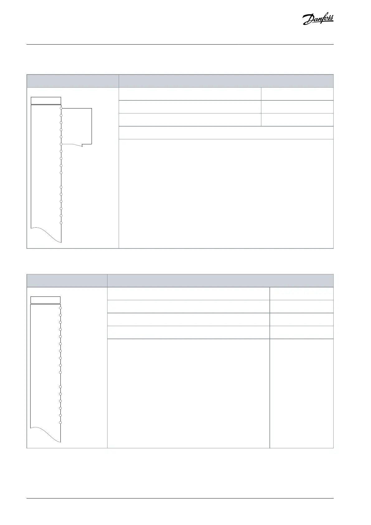
6.1.2 Wiring Configuration for Automatic Motor Adaptation (AMA)
Table 7: Wiring Configuration for AMA with T27 Connected
+24 V
+24 V
D IN
D IN
D IN
COM
D IN
D IN
D IN
D IN
+10 V
A IN
A IN
COM
A OUT
COM
12
13
18
19
20
27
29
32
33
37
50
53
54
55
42
39
e30bb929.11
Parameter 1-29 Automatic Motor Adaptation (AMA)
Parameter 5-12 Terminal 27 Digital Input
Notes/comments:
Set parameter group 1-2* Motor Data according to motor nameplate.
6.1.3 Wiring Configuration for Automatic Motor Adaptation without T27
Table 8: AMA without T27 Connected
Drive
+24 V
+24 V
D IN
D IN
D IN
COM
D IN
D IN
D IN
D IN
+10 V
A IN
A IN
COM
A OUT
COM
12
13
18
19
20
27
29
32
33
50
53
54
55
42
39
e30bb930.11
Parameter 1-29 Automatic Motor Adaptation (AMA)
Parameter 5-12 Terminal 27 Digital Input
Notes/comments:
Parameter group 1-2* Motor Data must be set according to motor.
AQ267037727118en-000101 / 130R030026 | Danfoss A/S © 2021.01
Basic I/O Configuration
VLT® AutomationDrive FC 301/FC 302
Operating Guide
 Loading...


