8.6.3 Analog Inputs
Switch S201 and switch S202
Switch S201/switch S202 = OFF (U)
-10 V to +10 V (scaleable)
Switch S201/S202 = ON (I)
Resolution for analog inputs
Accuracy of analog inputs
Maximum error 0.5% of full scale
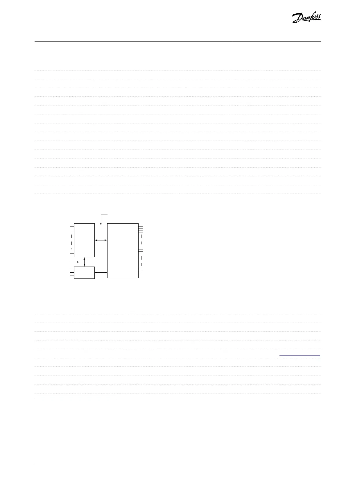
The analog inputs are galvanically isolated from the supply voltage (PELV) and other high-voltage terminals.
Functional
isolation
PELV isolation
Motor
DC-bus
High
voltage
+24 V
RS485
18
37
e30ba117.11
Illustration 20: PELV Isolation
8.6.4 Pulse/Encoder Inputs
Programmable pulse/encoder inputs
Terminal number pulse/encoder
29
(1)
, 33
(2)
/32
(3)
, 33
(3)
Maximum frequency at terminals 29, 32, 33
110 kHz (Push-pull driven)
Maximum frequency at terminals 29, 32, 33
Maximum frequency at terminals 29, 32, 33
See 8.6.1 Digital Inputs.
Pulse input accuracy (0.1–1 kHz)
Maximum error: 0.1% of full scale
Encoder input accuracy (1–11 kHz)
Maximum error: 0.05% of full scale
1
FC 302 only.
2
Pulse inputs are 29 and 33.
3
Encoder inputs: 32=A, 33=B.
The pulse and encoder inputs (terminals 29, 32, 33) are galvanically isolated from the supply voltage (PELV) and other high-voltage
terminals.
AQ267037727118en-000101 / 130R0300 | 73Danfoss A/S © 2021.01
Specifications
VLT® AutomationDrive FC 301/FC 302
Operating Guide
 Loading...


