EasyManuals Logo
Home>Danfoss>DC Drives>VLT AutomationDrive FC 301

Danfoss VLT AutomationDrive FC 301 Operating Guide

Danfoss VLT AutomationDrive FC 301
92 pages
To Next Page IconTo Next Page
To Previous Page IconTo Previous Page
Page #7 background imageLoading...
Page #7 background image
1.5.2 Exploded Views
1
2
3
4
5
6
7
8
9
10
11
12
13
16
17
18
19
14
6
FAN MOUNTING
QDF-30
DC-
DC+
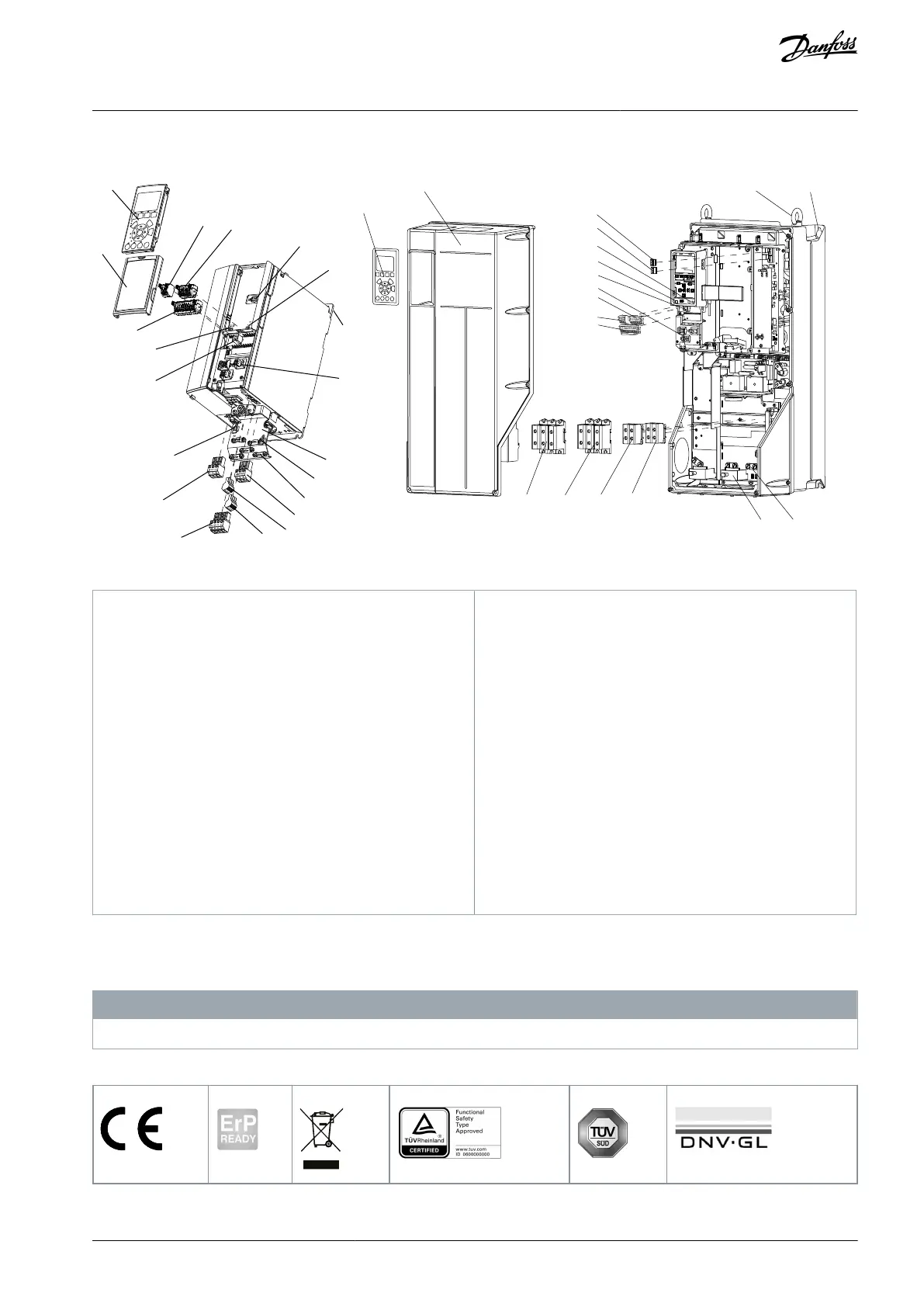
Remove jumper to activate Safe Stop
Max. 24 Volt !
12
19
32
33
20
37
06 05 04
03 02 01
130BF713.10
1
3
5
20
9
6
13
15
14
6
18
11
10
16, 17
19
14
7
8
4
2
Illustration 1: Exploded View Enclosure Size A, IP20 (left) and Enclosure Size C, IP55/IP66 (right)
1
Local control panel (LCP)
2
Cover
3
RS485 fieldbus connector
4
Digital input/output connector
5
Digital input/output connector
6
Shielded cable grounding and relief
7
USB connector
8
RS485 termination switch
9
DIP switch for A53 and A54
10
Relay 1 (01, 02, 03)
11
Relay 2 (04, 05, 06)
12
Lifting ring
13
Mounting slot
14
Ground connection (PE)
15
Cable shield connector
16
Brake terminal (-81, +82)
17
Load sharing terminal (-88, +89)
18
Motor terminals 96 (U), 97 (V), 98 (W)
19
Mains input terminals 91 (L1), 92 (L2), 93 (L3)
20
LCP connector
1.6 Type Approvals and Certifications
The following list is a selection of possible type approvals and certifications for Danfoss drives:
N O T I C E
Drives of enclosure size T7 (525–690 V) are not UL listed.
Table 2: Type Approvals and Certifications
AQ267037727118en-000101 / 130R0300 | 7Danfoss A/S © 2021.01
Introduction
VLT® AutomationDrive FC 301/FC 302
Operating Guide

Table of Contents

Other manuals for Danfoss VLT AutomationDrive FC 301

Questions and Answers:

Question and Answer IconNeed help?

Do you have a question about the Danfoss VLT AutomationDrive FC 301 and is the answer not in the manual?

Danfoss VLT AutomationDrive FC 301 Specifications

General IconGeneral
BrandDanfoss
ModelVLT AutomationDrive FC 301
CategoryDC Drives
LanguageEnglish

Related product manuals