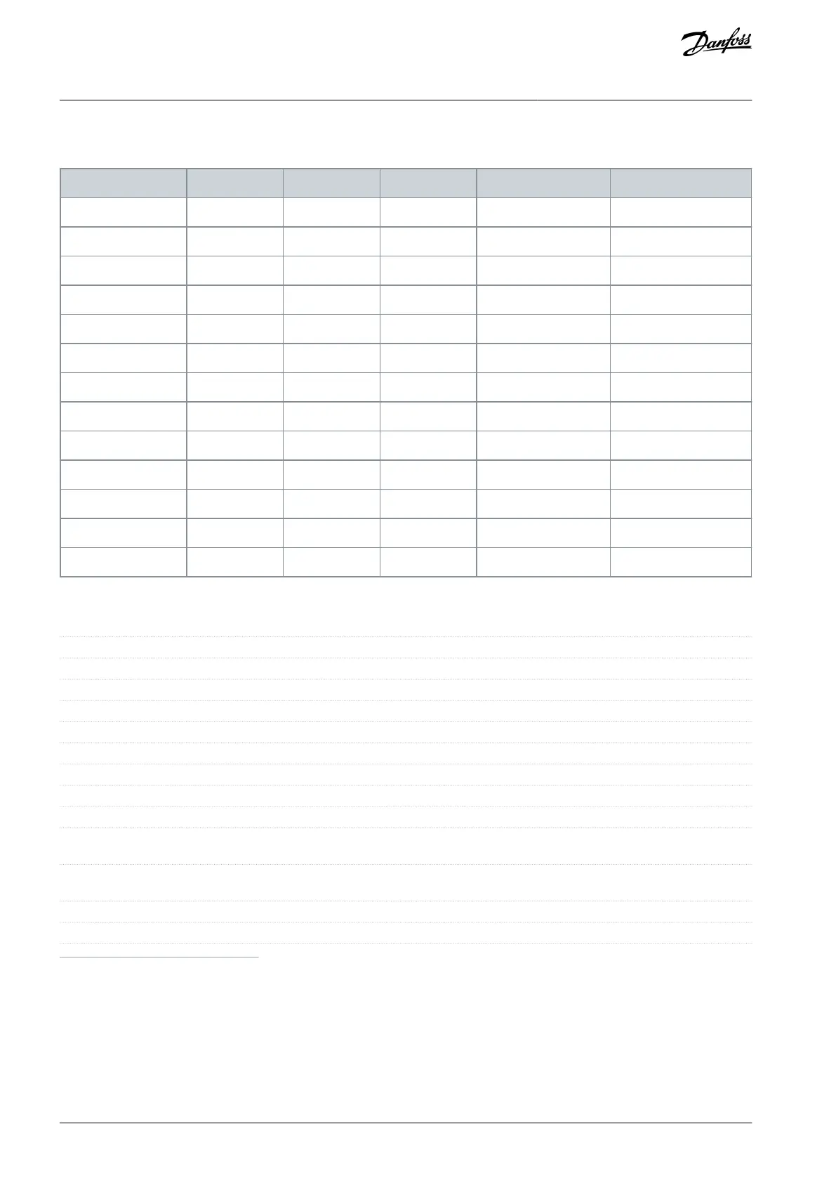
8.1.5 Power Cable Cross-sections
Table 41: Maximum Cable Cross-section [mm
2
(AWG)]
8.2 Mains Supply
Supply terminals (6-pulse)
Supply terminals (12-pulse)
L1-1, L2-1, L3-1, L1-2, L2-2, L3-2
FC 301: 380–480 V/FC 302: 380–500 V ±10%
Maximum imbalance temporary between mains phases
3.0% of rated supply voltage
≥0.9 nominal at rated load
Displacement power factor (cos Φ)
Switching on the input supply L1, L2, L3 (power-ups) ≤7.5 kW
(10 hp)
Switching on input supply L1, L2, L3 (power-ups) 11–75 kW (15–
101 hp)
Switching on input supply L1, L2, L3 (power-ups) ≥90 kW (121 hp)
Maximum once per 2 minutes
Environment according to EN60664-1
Overvoltage category III/pollution degree 2
1
Mains voltage low/mains dropout: During low mains voltage or a mains dropout, the drive continues until the DC-link voltage drops below the
minimum stop level, which typically corresponds to 15% below the drive's lowest rated supply voltage. Power-up and full torque cannot be exptec-
ted at mains voltage lower than 10% below the drive's lowest rated supply voltage.
2
The unit is suitable for use on a circuit capable of delivering not more than 100000 RMS symmetrical Amperes, 240/500/600/690 V maximum.
AQ267037727118en-000101 / 130R030070 | Danfoss A/S © 2021.01
Specifications
VLT® AutomationDrive FC 301/FC 302
Operating Guide

 Loading...


