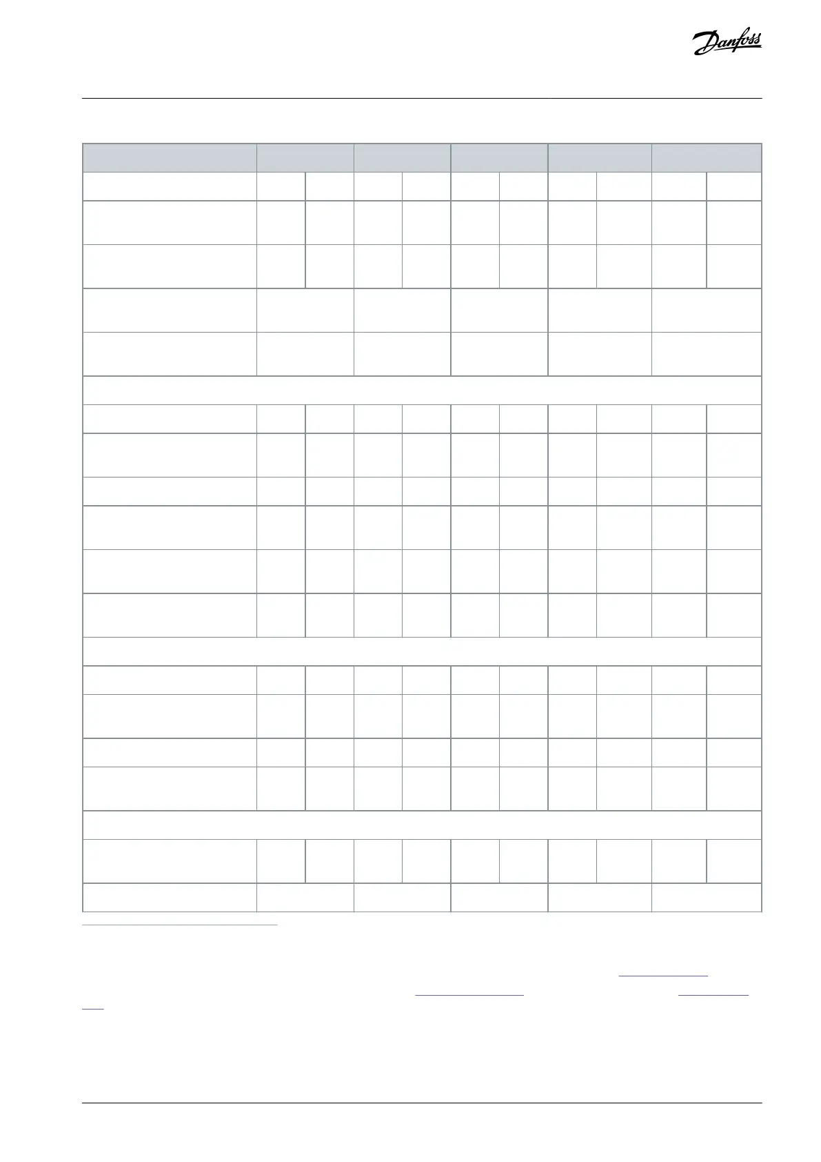
Table 40: B4, C2, C3 Enclosure, Mains Supply 525–690 V IP20/IP21/IP55 – Chassis/NEMA1/NEMA 12 (FC 302 only), P30K–P75K
Typical shaft output at 550 V
[kW/(hp)]
Typical shaft output at 690 V
[kW/(hp)]
Enclosure protection rating
IP20
Enclosure protection rating
IP21, IP55
Continuous (525–550 V) [A]
Intermittent (60 s overload)
(525–550 V) [A]
Continuous (551–690 V) [A]
Intermittent (60 s overload)
(551–690 V) [A]
Continuous kVA (at 550 V)
[kVA]
Continuous kVA (at 690 V)
[kVA]
Continuous (at 550 V) [A]
Intermittent (60 s overload) (at
550 V) [A]
Continuous (at 690 V) [A]
Intermittent (60 s overload) (at
690 V) [A]
Additional specifications
Estimated power loss at rated
maximum load [W]
(2)
1
High overload=150% or 160% torque for a duration of 60 s. Normal overload=110% torque for a duration of 60 s.
2
Applies for dimensioning of drive cooling. If the switching frequency is higher than the default setting, the power losses may increase. LCP and
typical control card power consumptions are included. For power loss data according to EN 50598-2, refer to Danfoss
MyDrive® ecoSmart website.
3
Efficiency measured at nominal current. For energy efficiency class, see 8.4 Ambient Conditions. For part load losses, see Danfoss MyDrive® ecoS-
mart website.
AQ267037727118en-000101 / 130R0300 | 69Danfoss A/S © 2021.01
Specifications
VLT® AutomationDrive FC 301/FC 302
Operating Guide
 Loading...


