PE
FC
PE
FC
130BB924.12
PE PE
69
69
68
68
1
2
<10 mm
1
Minimum 16 mm
2
(6 AWG)
2 Equalizing cable
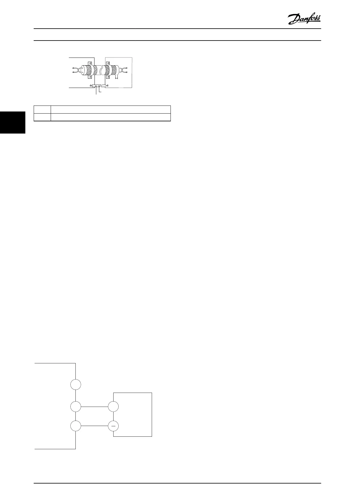
Illustration 4.11 Twisted-pair Cables without Terminal 61
4.7 Jumper Terminals 12 and 27
When the factory default programming values are used,
connect a jumper wire between terminal 12 and terminal
27 for the frequency converter to operate.
•
Digital input terminal 27 is designed to receive a
24 V DC coast command. In many applications,
wire a coast device to terminal 27.
•
When no interlock device is used, wire a jumper
between control terminal 12 and terminal 27. This
provides internal 24 V signal on terminal 27.
•
No signal present prevents the unit from
operating.
•
Only for GLCP: When the status line at the
bottom of the LCP reads AUTO REMOTE COAST, it
indicates that the unit is ready to operate but is
missing an input signal on terminal 27.
4.8
Serial Communication
Connect RS485 serial communication wiring to terminals
(+) 68 and (-) 69.
•
Shielded serial communication cable is
recommended.
•
See chapter 4.3.1 Grounding Requirements for
proper grounding.
Illustration 4.12 Serial Communication Wiring Diagram
For basic serial communication set-up, select the following:
1. Protocol type in parameter 8-30 Protocol.
2. Frequency converter address in
parameter 8-31 Address.
3. Baud rate in parameter 8-32 Baud Rate.
Two communication protocols are internal to the
frequency converter.
•
Danfoss FC
•
Modbus RTU
Follow motor manufacturer wiring requirements.
Functions can be programmed remotely using the protocol
software and RS485 connection, or in parameter group 8-**
Communications and Options.
Selecting a
specic communication protocol changes
various default parameter settings to match the speci-
cations of the protocol and makes extra protocol-specic
parameters available.
Electrical Installation
VLT
®
AutomationDrive FC 360
20 Danfoss A/S © 03/2017 All rights reserved. MG06A702
44
 Loading...


