VLT
®
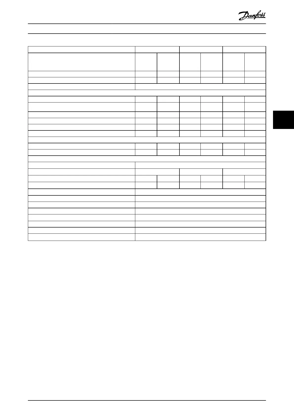
AutomationDrive FC 361
N200 N250 N315
High/normal overload HO NO HO NO HO NO
(High overload=150% current during 60 s, normal
overload=110% current during 60 s)
Typical shaft output at 400 V [kW] 160 200 200 250 250 315
Typical shaft output at 460 V [hp] 250 300 300 350 350 450
Enclosure size J9
Output current (3-phase)
Continuous (at 400 V) [A] 315 395 395 480 480 588
Intermittent (60 s overload) (at 400 V) [A]
473 435 593 528 720 647
Continuous (at 460 V) [A] 302 361 361 443 443 535
Intermittent (60 s overload) (at 460 V) [kVA] 453 397 542 487 665 589
Continuous kVA (at 400 V) [kVA] 218 274 274 333 333 407
Continuous kVA (at 460 V) [kVA] 241 288 288 353 353 426
Maximum input current
Continuous (at 400 V) [A] 304 381 381 463 463 567
Continuous (at 460 V) [A] 291 348 348 427 427 516
Maximum number and size of cables per phase
Mains and motor [mm
2
(AWG)]
2x185 (2x350 mcm)
Maximum external mains fuses [A]
1)
550 630 800
Estimated power loss at 400 V [W]
2), 3)
3093 4116 4039 5137 5004 6674
Estimated power loss at 460 V [W]
2), 3)
2872 3569 3575 4566 4458 5714
Eciency
3)
0.98
Output frequency [Hz] 0–590
Heat sink overtemperature trip [°C (°F)]
110 (230)
Weight, enclosure protection rating IP20 kg (lbs) 164 (362)
Eciency
3)
0.98
Output frequency [Hz] 0–590
Heat sink overtemperature trip [°C (°F)]
110 (230)
Control card overtemperature trip [°C (°F)]
80 (176)
Table 5.2 Electrical Data for Enclosures J9, Mains Supply 3x380–480 V AC
1) For fuse ratings, see chapter 7.5 Fuses and Circuit Breakers.
2) Typical power loss is at normal conditions and expected to be within
±
15% (tolerance relates to variety in voltage and cable conditions). These
values are based on a typical motor eciency (IE/IE3 border line). Lower eciency motors add to the power loss in the drive. Applies to
dimensioning of drive cooling. If the switching frequency is higher than the default setting, the power losses can increase. LCP and typical control
card power consumptions are included. For power loss data according to EN 50598-2, refer to drives.danfoss.com/knowledge-center/energy-
eciency-directive/#/. Options and customer load can add up to 30 W to the losses, though usually a fully loaded control card and options for
slots A and B each add only 4 W.
3) Measured using 5 m (16.4 ft) shielded motor cables at rated load and rated frequency. Eciency measured at nominal current. For energy
eciency class, see chapter 5.4 Ambient Conditions. For part load losses, see drives.danfoss.com/knowledge-center/energy-eciency-directive/#/.
Specications Design Guide
MG06K102 Danfoss A/S © 03/2019 All rights reserved. 17
5 5
 Loading...


