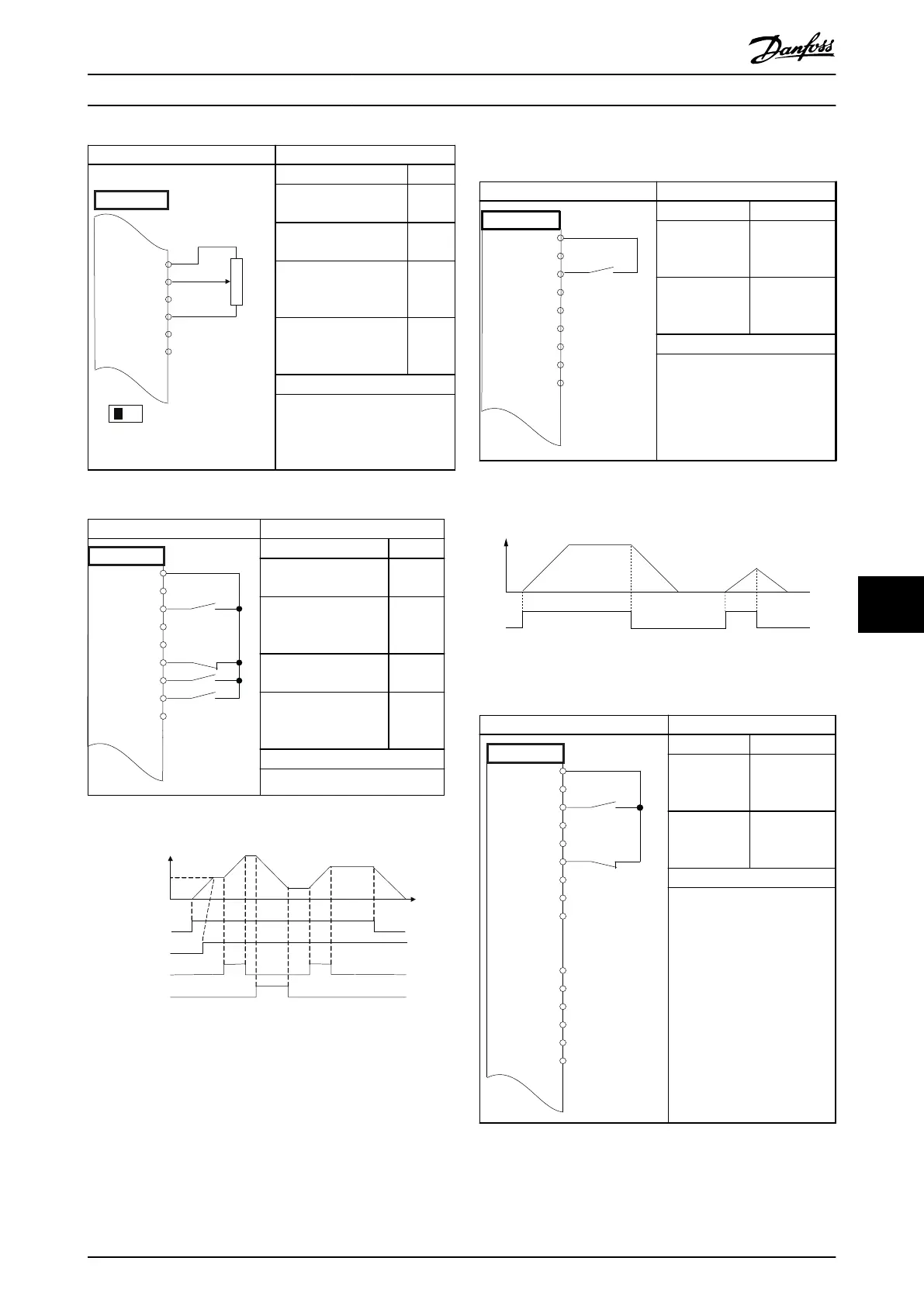
Parameters
A IN
A IN
COM
A OUT
COM
50
53
54
55
42
39
A53
U - I
≈ 5kΩ
e30bb683.11
FC
Function Setting
Parameter 6-12 Terminal
53 Low Current
4 mA*
Parameter 6-13 Terminal
53 High Current
20 mA*
Parameter 6-14 Terminal
53 Low Ref./Feedb.
Value
0 Hz
Parameter 6-15 Terminal
53 High Ref./Feedb.
Value
50 Hz
* = Default value
Notes/comments:
Assumptions are 0 V DC input
= 0 RPM speed and 10 V DC
input = 1500 RPM speed.
Table 9.3 Speed Reference (Using a Manual Potentiometer)
Parameters
FC
+24 V
+24 V
D IN
D IN
D IN
COM
D IN
D IN
D IN
12
13
18
19
20
27
29
32
33
e30bg503.10
Function Setting
Parameter 5-10 Termin
al 18 Digital Input
[8] Start*
Parameter 5-12 Termin
al 27 Digital Input
[19]
Freeze
Reference
Parameter 5-13 Termin
al 29 Digital Input
[21]
Speed Up
Parameter 5-14 Termin
al 32 Digital Input
[22]
Speed
Down
* = Default value
Notes/comments:
Table 9.4 Speed Up/Speed Down
130BB840.12
Speed
Reference
Start (18)
Freeze ref (27)
Speed up (29)
Speed down (32)
Illustration 9.2 Speed Up/Speed Down
9.3 Wiring for Start/Stop
Parameters
FC
+24 V
+24 V
D IN
D IN
D IN
COM
D IN
D IN
D IN
12
13
18
19
20
27
29
32
33
e30bg504.10
Function Setting
Parameter 5-10
Terminal 18
Digital Input
[8] Start*
Parameter 5-12
Terminal 27
Digital Input
[0] No
operation
* = Default value
Notes/comments:
If parameter 5-12 Terminal 27
Digital Input is set to [0] No
operation, a jumper wire to
terminal 27 is not needed.
Table 9.5 Start/Stop Command
130BB805.12
Speed
Start/Stop (18)
Illustration 9.3 Start/Stop Command
Parameters
FC
+24 V
+24 V
D IN
D IN
D IN
COM
D IN
D IN
D IN
+10 V
A IN
A IN
COM
A OUT
COM
12
13
18
19
20
27
29
32
33
50
53
54
55
42
39
e30bg505.10
Function Setting
Parameter 5-1
0 Terminal 18
Digital Input
[9] Latched
Start
Parameter 5-1
2 Terminal 27
Digital Input
[6] Stop Inverse
* = Default value
Notes/comments:
Table 9.6 Pulse Start/Stop
Application Examples Design Guide
MG06K102 Danfoss A/S © 03/2019 All rights reserved. 69
9 9
 Loading...


