5 Specications
5.1 Electrical Data, 380-480 V
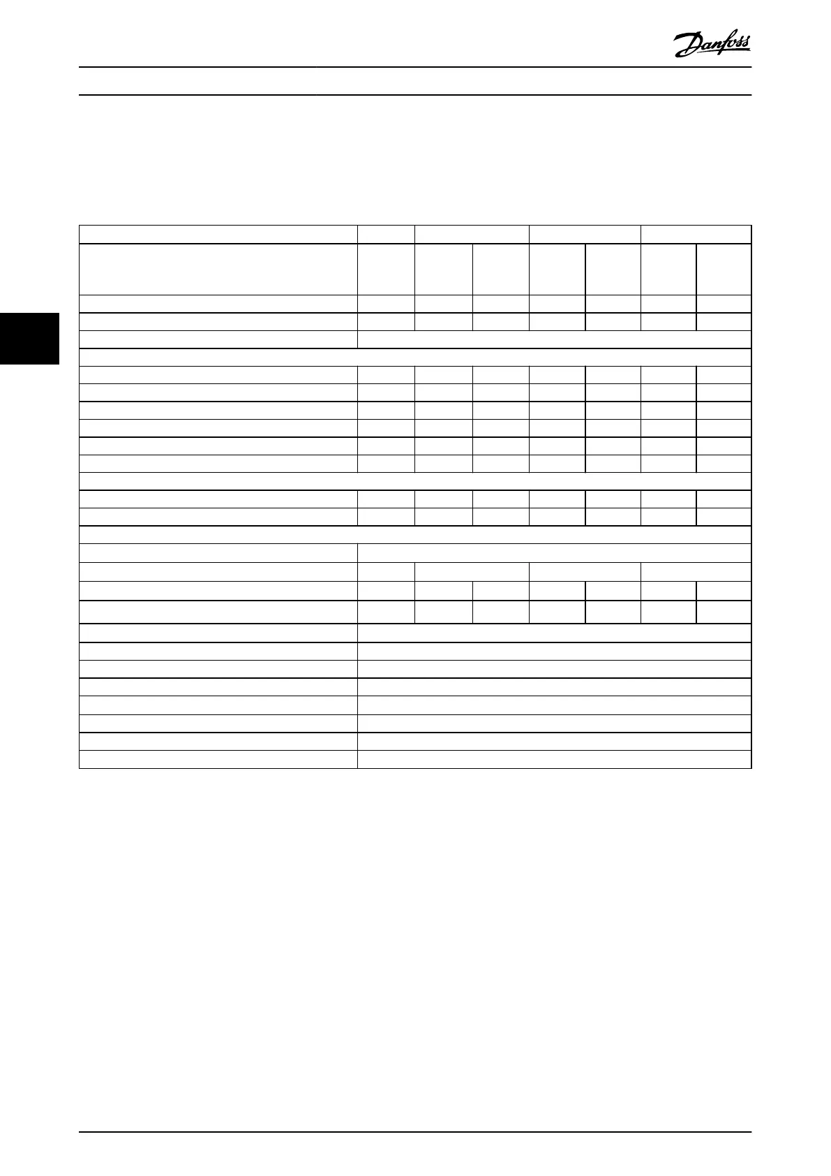
VLT
®
AutomationDrive FC 361
N90K N110 N132 N160
High/normal overload NO HO NO HO NO HO NO
(High overload=150% current during 60 s, normal
overload=110% current during 60 s)
Typical shaft output at 400 V [kW] 90 90 110 110 132 132 160
Typical shaft output at 460 V [hp] 125 125 150 150 200 200 250
Enclosure size J8
Output current (3-phase)
Continuous (at 400 V) [A] 177 177 212 212 260 260 315
Intermittent (60 s overload) (at 400 V) [A] 195 266 233 318 286 390 347
Continuous (at 460 V) [A] 160 160 190 190 240 240 302
Intermittent (60 s overload) (at 460 V) [kVA] 176 240 209 285 264 360 332
Continuous kVA (at 400 V) [kVA] 123 123 147 147 180 180 218
Continuous kVA (at 460 V) [kVA] 127 127 151 151 191 191 241
Maximum input current
Continuous (at 400 V) [A] 171 171 204 204 251 251 304
Continuous (at 460 V) [A] 154 154 183 183 231 231 291
Maximum number and size of cables per phase
Mains and motor [mm
2
(AWG)]
2x95 (2x3/0)
Maximum external mains fuses [A]
1)
315 315 350 400
Estimated power loss at 400 V [W]
2), 3)
2031 2031 2559 2289 2954 2923 3770
Estimated power loss at 460 V [W]
2), 3)
1828 1828 2261 2051 2724 2089 3628
Eciency
3)
0.98
Output frequency [Hz] 0–590
Heat sink overtemperature trip [°C (°F)]
110 (230)
Weight, enclosure protection rating IP20 kg (lbs) 98 (216)
Eciency
3)
0.98
Output frequency [Hz] 0–590
Heat sink overtemperature trip [°C (°F)]
110 (230)
Control card overtemperature trip [°C (°F)]
75 (167)
Table 5.1 Electrical Data for Enclosures J8, Mains Supply 3x380–480 V AC
1) For fuse ratings, see chapter 7.5 Fuses and Circuit Breakers.
2) Typical power loss is at normal conditions and expected to be within
±
15% (tolerance relates to variety in voltage and cable conditions). These
values are based on a typical motor eciency (IE/IE3 border line). Lower eciency motors add to the power loss in the drive. Applies to
dimensioning of drive cooling. If the switching frequency is higher than the default setting, the power losses can increase. LCP and typical control
card power consumptions are included. For power loss data according to EN 50598-2, refer to drives.danfoss.com/knowledge-center/energy-
eciency-directive/#/. Options and customer load can add up to 30 W to the losses, though usually a fully loaded control card and options for
slots A and B each add only 4 W.
3) Measured using 5 m (16.4 ft) shielded motor cables at rated load and rated frequency. Eciency measured at nominal current. For energy
eciency class, see chapter 5.4 Ambient Conditions. For part load losses, see drives.danfoss.com/knowledge-center/energy-eciency-directive/#/.
Specications VLT® AutomationDrive FC 361
16 Danfoss A/S © 03/2019 All rights reserved. MG06K102
55
 Loading...


