11.10 RS485: Modbus RTU Parameters
11.10.1 Parameter Handling
The PNU (parameter number) is translated from the
register address contained in the Modbus read or write
message. The parameter number is translated to Modbus
as (10xparameter number) DECIMAL.
11.10.2 Storage of Data
The coil 65 decimal determines whether data written to
the drive is stored in EEPROM and RAM (coil 65=1) or only
in RAM (coil 65=0).
11.10.3 IND
The array index is set in holding register 9 and used when
accessing array parameters.
11.10.4 Text Blocks
Parameters stored as text strings are accessed in the same
way as the other parameters. The maximum text block size
is 20 characters. If a read request for a parameter is for
more characters than the parameter stores, the response is
truncated. If the read request for a parameter is for fewer
characters than the parameter stores, the response is space
lled.
11.10.5 Conversion Factor
Since a parameter value can only be transferred as a whole
number, a conversion factor must be used to transfer
decimals. See chapter 11.6 RS485: FC Protocol Parameter
Examples.
11.10.6 Parameter Values
Standard data types
Standard data types are int16, int32, uint8, uint16, and
uint32. They are stored as 4x registers (40001–4FFFF). The
parameters are read using function 03 hex read holding
registers. Parameters are written using the function 6 hex
preset single register for 1 register (16 bits), and the
function 10 hex preset multiple registers for 2 registers (32
bits). Readable sizes range from 1 register (16 bits) up to
10 registers (20 characters).
Non-standard data types
Non-standard data types are text strings and are stored as
4x registers (40001–4FFFF). The parameters are read using
function 03 hex Read holding registers and written using
function 10 hex Preset multiple registers. Readable sizes
range from 1 register (2 characters) up to 10 registers (20
characters).
11.11
RS485: FC Control Prole
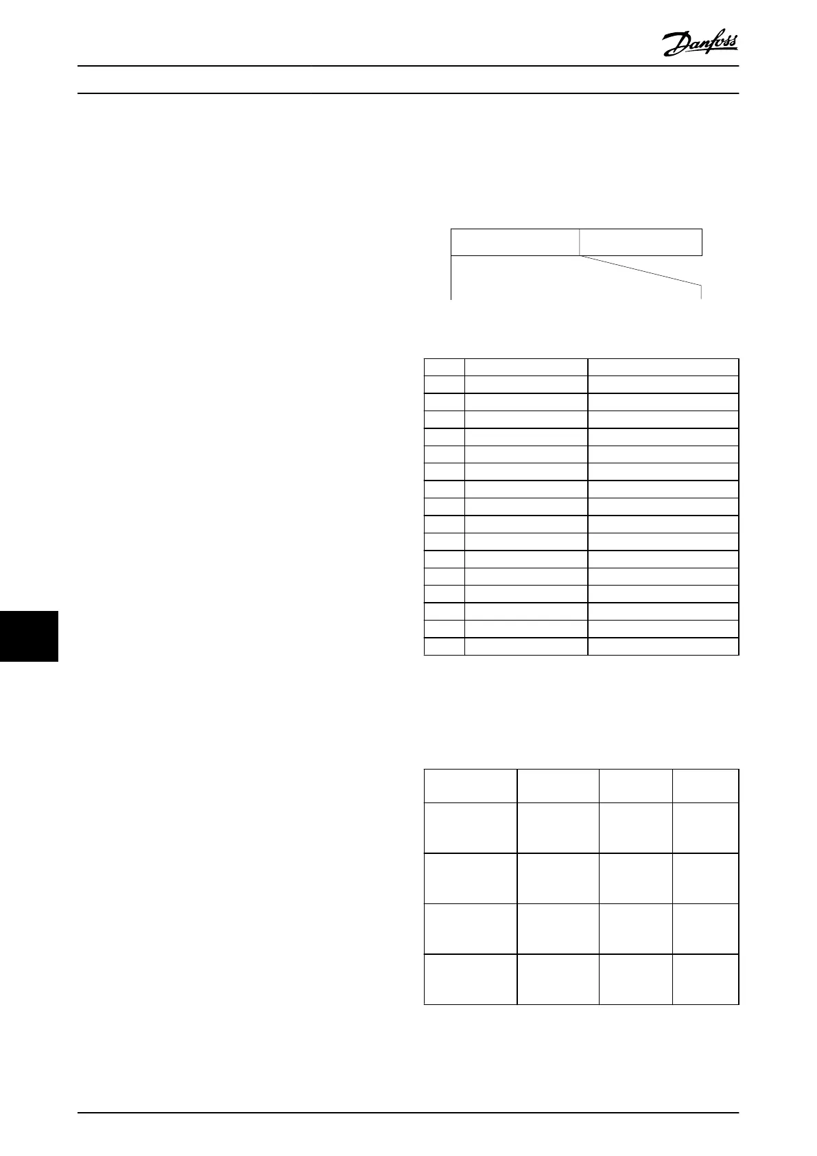
11.11.1 Control Word According to FC
Prole
Speed ref.CTW
Master-follower
130BA274.11
15 14 13 12 11 10 9 8 7 6 5 4 3 2 1 0
Bit
no.:
Illustration 11.16 CW Master-to-Slave
Bit Bit value = 0 Bit value = 1
00 Reference value External selection lsb
01 Reference value External selection msb
02 DC brake Ramp
03 Coasting No coasting
04 Quick stop Ramp
05 Hold output frequency Use ramp
06 Ramp stop Start
07 No function Reset
08 No function Jog
09 Ramp 1 Ramp 2
10 Data invalid Data valid
11 No function Relay 01 active
12 No function Relay 02 active
13 Parameter set-up Selection lsb
14 Parameter set-up Selection msb
15 No function Reverse
Explanation of the control bits
Bits 00/01
Bits 00 and 01 are used to select between the 4 reference
values, which are pre-programmed in parameter 3-10 Preset
Reference according to Table 11.20.
Programmed
reference value
Parameter Bit 01 Bit 00
1 [0]
parameter 3-10
Preset Reference
0 0
2 [1]
parameter 3-10
Preset Reference
0 1
3 [2]
parameter 3-10
Preset Reference
1 0
4 [3]
parameter 3-10
Preset Reference
1 1
Table 11.20 Control Bits
Appendix VLT® AutomationDrive FC 361
88 Danfoss A/S © 03/2019 All rights reserved. MG06K102
1111
 Loading...


