9.5 Wiring for a Motor Thermistor
WARNING
THERMISTOR INSULATION
Risk of personal injury or equipment damage.
•
To meet PELV insulation requirements, use only
thermistors with reinforced or double
insulation.
Parameters
e30bg507.10
VLT
+24 V
+24 V
D IN
D IN
D IN
COM
D IN
D IN
D IN
+10 V
A IN
A IN
COM
A OUT
COM
12
13
18
19
20
27
29
32
33
50
53
54
55
42
39
A53
U - I
Function Setting
Parameter 1-90
Motor Thermal
Protection
[2] Thermistor
trip
Parameter 1-93
Thermistor
Resource
[1] Analog
input 53
* = Default value
Notes/comments:
If only a warning is desired, set
parameter 1-90 Motor Thermal
Protection to [1] Thermistor
warning.
Table 9.9 Motor Thermistor
9.6
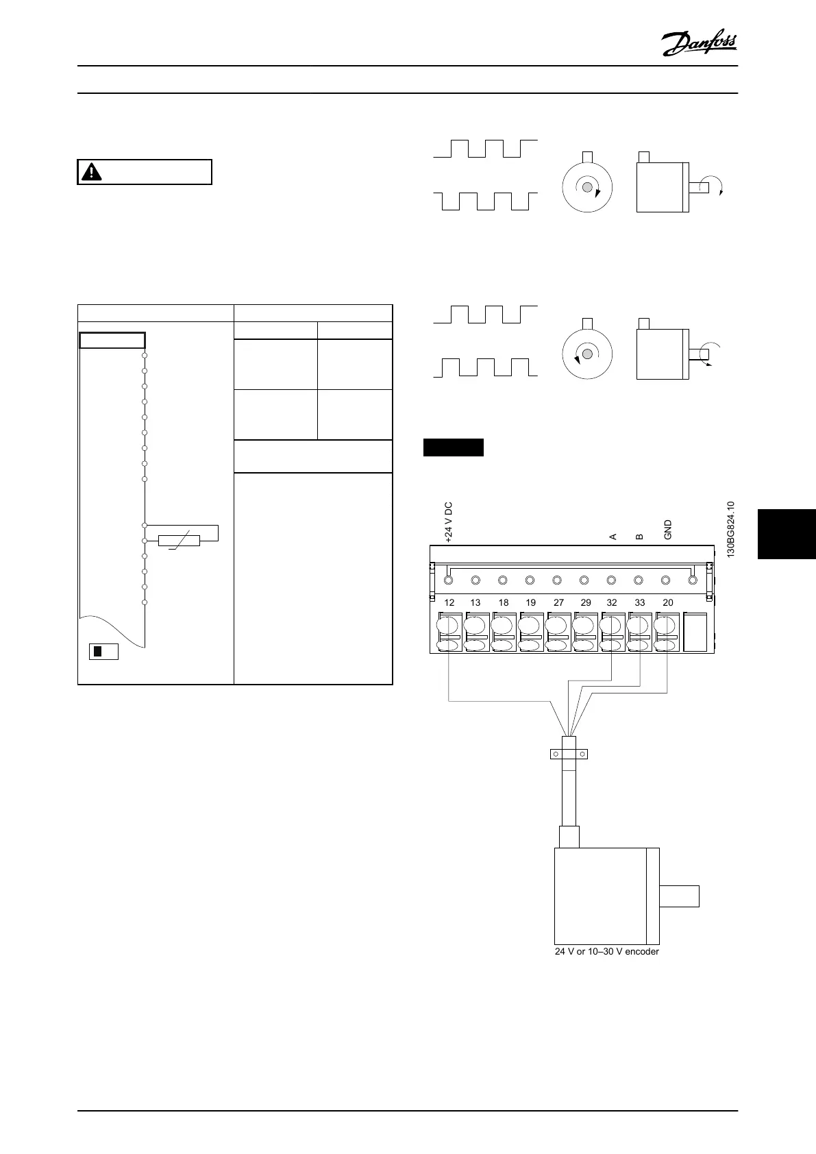
Wiring Conguration for the Encoder
The direction of the encoder, identied by looking into the
shaft end, is determined by which order the pulses enter
the drive. See Illustration 9.5.
•
Clockwise (CW) direction means channel A is 90
electrical degrees before channel B.
•
Counterclockwise (CCW) direction means channel
B is 90 electrical degrees before A.
Illustration 9.5 Determining Encoder Direction
NOTICE
Maximum cable length 5 m (16 ft).
Illustration 9.6 Wire Conguration for the Encoder
Application Examples Design Guide
MG06K102 Danfoss A/S © 03/2019 All rights reserved. 71
9 9
 Loading...


