5.8 Control Wiring
All terminals to the control cables are inside the drive
below the LCP. To access the control terminals, remove the
front panel.
5.8.1 Control Cable Routing
•
Isolate control wiring from high-power
components in the drive.
•
Tie down all control wires after routing them.
•
Connect shields to ensure optimum electrical
immunity.
•
When the drive is connected to a thermistor,
ensure that the thermistor control wiring is
shielded and reinforced/double insulated. A 24 V
DC supply voltage is recommended.
Fieldbus connection
Connections are made to the relevant options on the
control card. For more detail, see the relevant eldbus
instruction. The cable must be tied down and routed along
with other control wires inside the unit.
5.8.2 Control Terminal Types
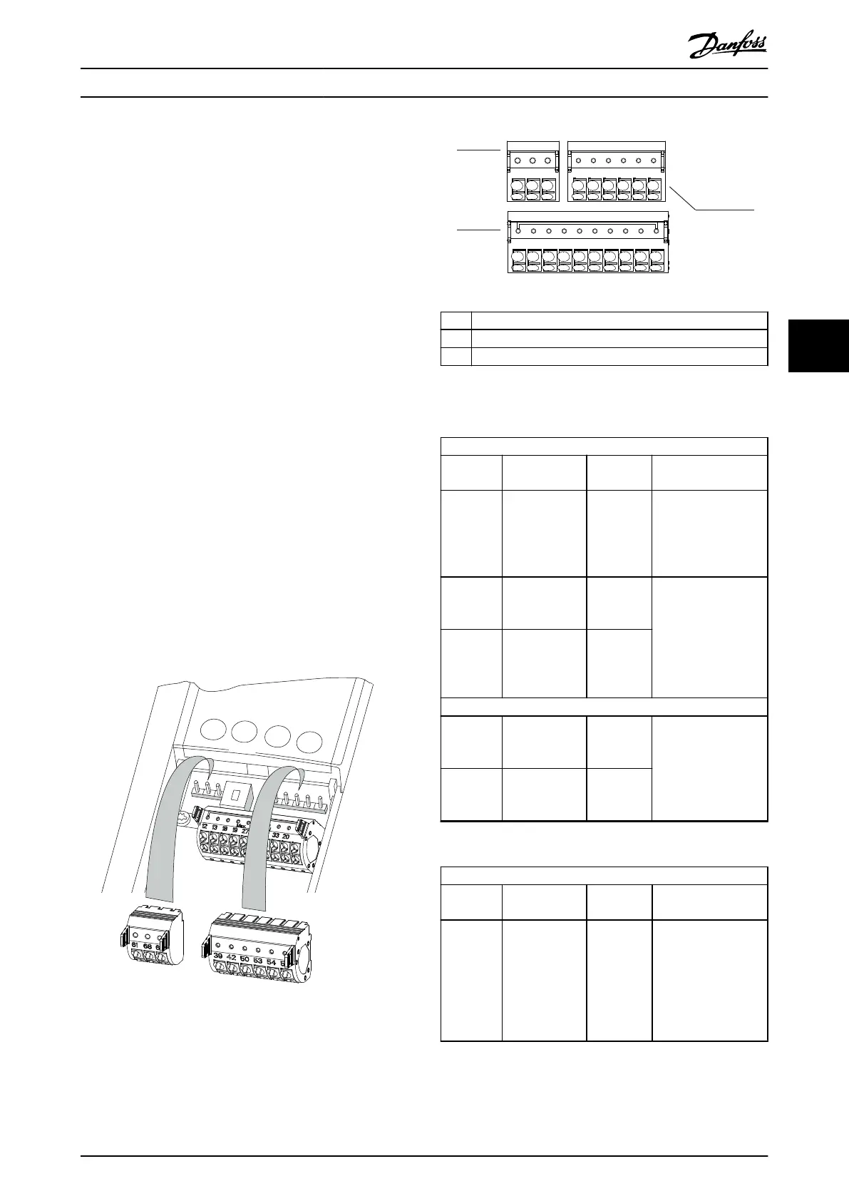
Illustration 5.10 shows the removable drive connectors.
Terminal functions and default settings are summarized in
Table 5.1 – Table 5.3.
Illustration 5.10 Control Terminal Locations
12 13 18 19 27 29 32 33 20
39696861 42 50 53 54 55
e30bg502.10
1
2
3
1 Serial communication terminals
2 Digital input/output terminals
3 Analog input/output terminals
Illustration 5.11 Terminal Numbers Located on the Connectors
Serial communication terminals
Terminal Parameter Default
setting
Description
61 – – Integrated RC-lter for
cable shield. ONLY for
connecting the shield
in the event of EMC
problems.
68 (+) Parameter
group 8-3* FC
Port Settings
– RS485 interface. A
switch (BUS TER.) is
provided on the
control card for bus
termination
resistance. See
Illustration 5.16.
69 (-) Parameter
group 8-3* FC
Port Settings
–
Relays
01, 02, 03 Parameter 5-40
Function Relay
[0]
[0] No
operation
Form C relay output.
For AC or DC voltage
and resistive or
inductive loads.
04, 05, 06 Parameter 5-40
Function Relay
[1]
[0] No
operation
Table 5.1 Serial Communication Terminal Descriptions
Digital input/output terminals
Terminal Parameter Default
setting
Description
12, 13 – +24 V DC 24 V DC supply
voltage for digital
inputs and external
transducers.
Maximum output
current 200 mA for all
24 V loads.
Electrical Installation Operating Guide
MG06I102 Danfoss A/S © 06/2018 All rights reserved. 31
5 5
 Loading...


