3 = Third from the left inverter module.
4 = Far right inverter module.
5 = Rectier module.
6 = Right rectier module.
ALARM 247, Power card temperature
The supply on the power card is out of range.
The report value in the alarm log indicates which power
module generated the alarm:
1 = Leftmost inverter module.
2 = Middle inverter module.
2 = Right inverter module.
2 = Second drive from the left inverter module.
3 = Right inverter module.
3 = Third from the left inverter module.
4 = Far right inverter module.
5 = Rectier module.
6 = Right rectier module.
ALARM 248, Illegal power section conguration
Power size conguration fault on the power card.
The report value in the alarm log indicates which power
module generated the alarm:
1 = Leftmost inverter module.
2 = Middle inverter module.
2 = Right inverter module.
2 = Second drive from the left inverter module.
3 = Right inverter module.
3 = Third from the left inverter module.
4 = Far right inverter module.
5 = Rectier module.
6 = Right rectier module.
WARNING 249, Rect. low temperature
The temperature of the rectier heat sink is too low, which
indicates that the temperature sensor may be defect.
WARNING 250, New spare part
The power or switch mode supply has been exchanged.
Restore the drive type code in the EEPROM. Select the
correct type code in parameter 14-23 Typecode Setting
according to the label on the drive. Remember to select
Save to EEPROM at the end.
WARNING 251, New typecode
The power card or other components are replaced, and the
type code has changed.
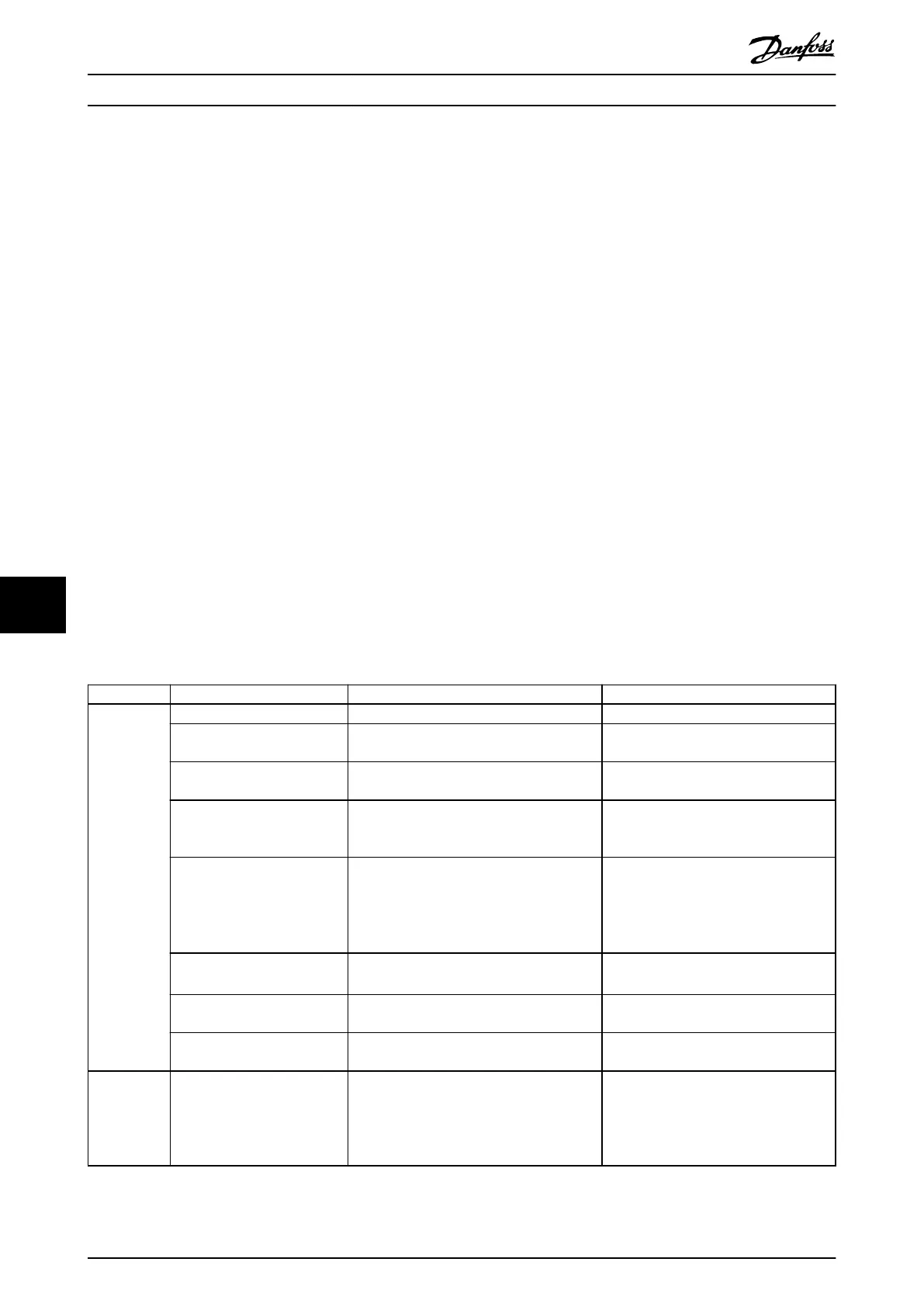
9.6
Troubleshooting
Symptom Possible cause Test Solution
Display
dark/No
function
Missing input power. See Table 6.1. Check the input power source.
Missing or open fuses. See Open power fuses in this table for possible
causes.
Follow the recommendations provided.
No power to the LCP. Check the LCP cable for proper connection or
damage.
Replace the faulty LCP or connection
cable.
Shortcut on control voltage
(terminal 12 or 50) or at control
terminals.
Check the 24 V control voltage supply for
terminal 12/13 to 20–39, or 10 V supply for
terminals 50–55.
Wire the terminals properly.
Incompatible LCP (Check if an
incompatible LCP from VLT
®
2800 or 5000/6000/8000/ FCD
or FCM is used in this
frequency converter).
– Use only LCP 101 (P/N 130B1124) or LCP
102 (P/N 130B1107).
Wrong contrast setting. –
Press [Status] + [
▲
]/[
▼
] to adjust the
contrast.
Display (LCP) is defective. Test using a dierent LCP. Replace the faulty LCP or connection
cable.
Internal voltage supply fault or
SMPS is defective.
– Contact supplier.
Intermittent
display
Overloaded supply (SMPS) due
to improper control wiring or a
fault within the AC drive.
To rule out a problem in the control wiring,
disconnect all control wiring by removing the
terminal blocks.
If the display stays lit, the problem is in
the control wiring. Check the wiring for
shorts or incorrect connections. If the
display continues to cut out, follow the
procedure for Display dark/No function.
Maintenance, Diagnostics, a... VLT® AutomationDrive FC 361
54 Danfoss A/S © 06/2018 All rights reserved. MG06I102
99
 Loading...


