11 Appendix
11.1 Abbreviations and Conventions
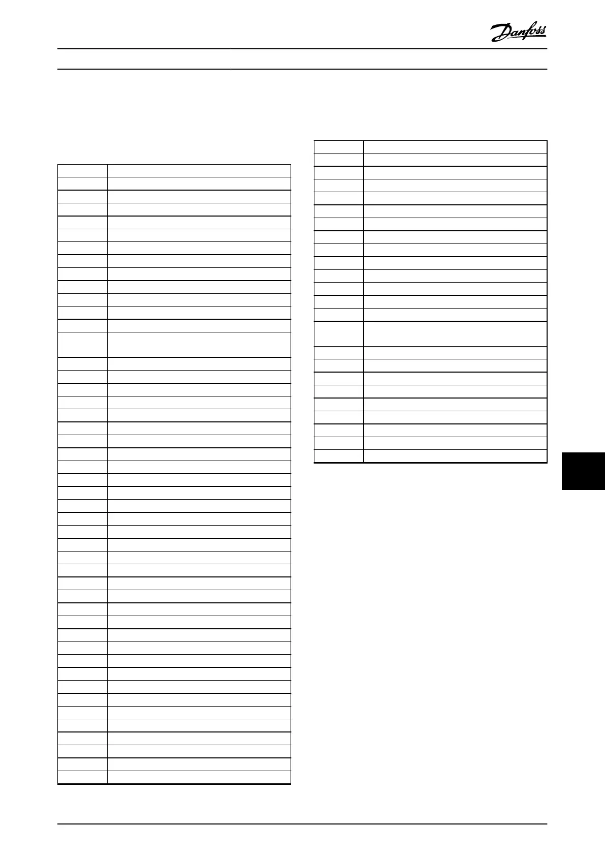
°C
Degrees Celsius
°F
Degrees Fahrenheit
Ω
Ohm
AC Alternating current
AEO Automatic energy optimization
ACP Application control processor
AMA Automatic motor adaptation
AWG American wire gauge
CPU Central processing unit
CSIV Customer-specic initialization values
CT Current transformer
DC Direct current
DVM Digital voltmeter
EEPROM
Electrically erasable programmable read-only
memory
EMC Electromagnetic compatibility
EMI Electromagnetic interference
ESD Electrostatic discharge
ETR Electronic thermal relay
f
M,N
Nominal motor frequency
HF High frequency
HVAC Heating, ventilation, and air conditioning
Hz Hertz
I
LIM
Current limit
I
INV
Rated inverter output current
I
M,N
Nominal motor current
I
VLT,MAX
Maximum output current
I
VLT,N
Rated output current supplied by the drive
IEC International electrotechnical commission
IGBT Insulated-gate bipolar transistor
I/O Input/output
IP Ingress protection
kHz Kilohertz
kW Kilowatt
L
d
Motor d-axis inductance
L
q
Motor q-axis inductance
LC Inductor-capacitor
LCP Local control panel
LED Light-emitting diode
LOP Local operation pad
mA Milliamp
MCB Miniature circuit breakers
MCP Motor control processor
mV Millivolts
NEMA National Electrical Manufacturers Association
NTC Negative temperature coecient
P
M,N
Nominal motor power
PCB Printed circuit board
PE Protective earth
PELV Protective extra low voltage
PID Proportional integral derivative
PLC Programmable logic controller
P/N Part number
PROM Programmable read-only memory
PS Power section
PTC Positive temperature coecient
PWM Pulse width modulation
R
s
Stator resistance
RAM Random-access memory
RCD Residual current device
Regen Regenerative terminals
RFI Radio frequency interference
RMS
Root means square (cyclically alternating electric
current)
RPM Revolutions per minute
SCR Silicon controlled rectier
SMPS Switch mode power supply
S/N Serial number
T
LIM
Torque limit
U
M,N
Nominal motor voltage
V Volt
VVC Voltage vector control
X
h
Motor main reactance
Table 11.1 Abbreviations, Acronyms, and Symbols
Conventions
•
Numbered lists indicate procedures.
•
Bullet lists indicate other information and
description of illustrations.
•
Italicized text indicates:
- Cross reference
- Link
- Footnote
- Parameter name
- Parameter group name
- Parameter option
•
All dimensions are in mm (inch).
11.2
Parameter Menu Structure
Appendix Operating Guide
MG06I102 Danfoss A/S © 06/2018 All rights reserved. 71
11 11
 Loading...


