2.1.8. Safe Stop Installation
To carry out an installation of a Catego-
ry 0 Stop (EN60204) in conformity with
Safety Category 3 (EN954-1), follow
these instructions:
1. The bridge (jumper) between Termi-
nal 37 and 24 V DC must be re-
moved. Cutting or breaking the
jumper is not sufficient. Remove it
entirely to avoid short-circuiting. See
jumper on illustration.
2. Connect terminal 37 to 24 V DC by a
short circuit-protected cable. The 24
V DC voltage supply must be inter-
ruptible by an EN954-1 category 3
circuit interrupt device. If the inter-
rupt device and the adjustable fre-
quency drive are placed in the same
installation panel, you can use an un-
shielded cable instead of a shielded
one.
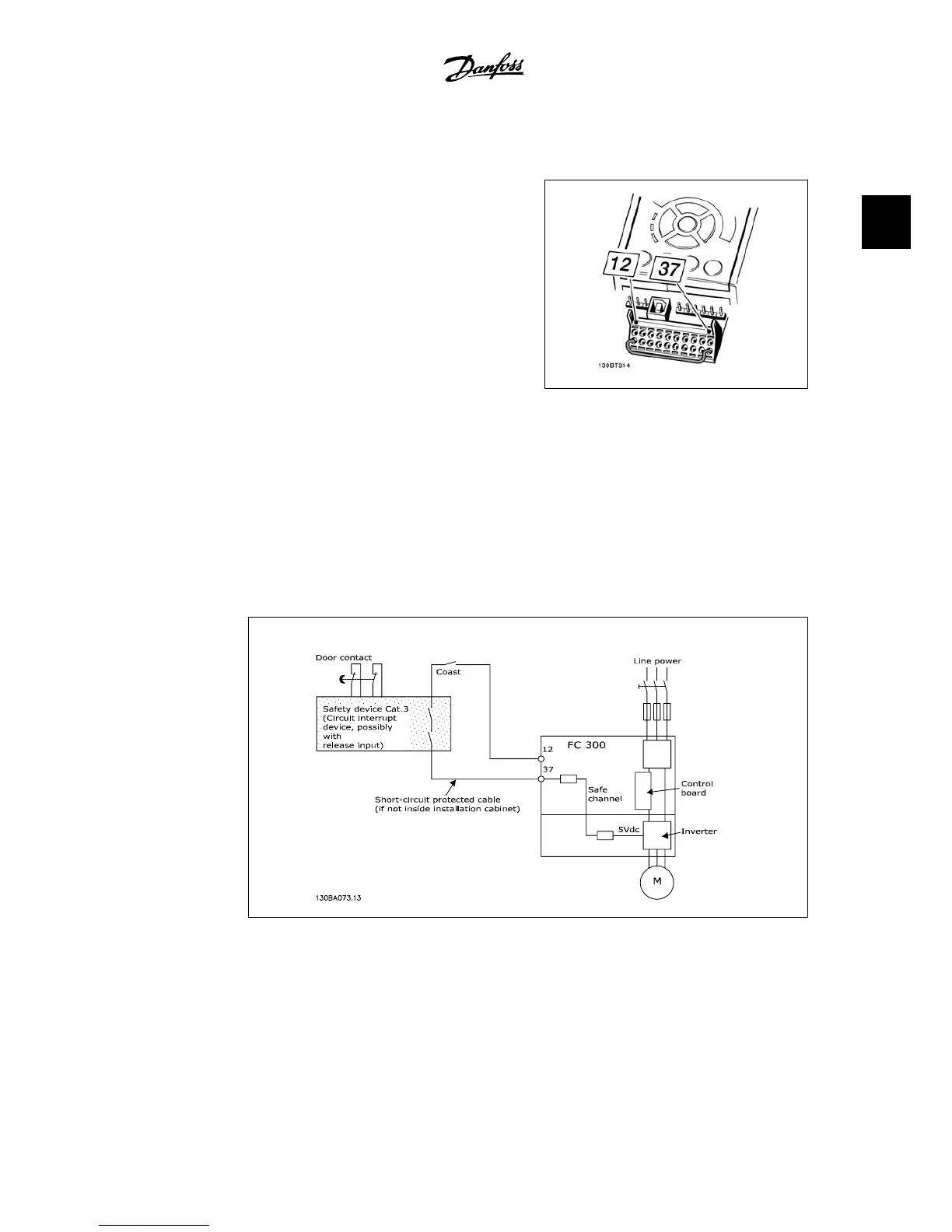
2.1: Bridge jumper between terminal 37 and 24
VDC
The illustration below shows a Stopping Category 0 (EN 60204-1) with safety Category 3 (EN
954-1). The circuit interruption is caused by an opening door contact. The illustration also shows
how to connect a non-safety-related hardware coast.
2.2: Illustration of the essential aspects of an installation to achieve a Stopping Category 0 (EN 60204-1)
with safety Category 3 (EN 954-1).
2.1.9. IT Line
Par. 14-50
RFI 1
can be used on the FC 102/202/302 to disconnect the internal RFI capacitors
from the RFI filter to ground. If this is done, it will reduce the RFI performance to A2 level.
VLT
®
Automation Drive FC 300
Instruction Manual High Power
2. Safety Instructions and General Warning
MG.33.U1.22 - VLT
®
is a registered Danfoss trademark.
11
2
 Loading...


