3.3.6. Gland/Conduit Entry - IP 21 (NEMA 1) and IP 54 (NEMA12)
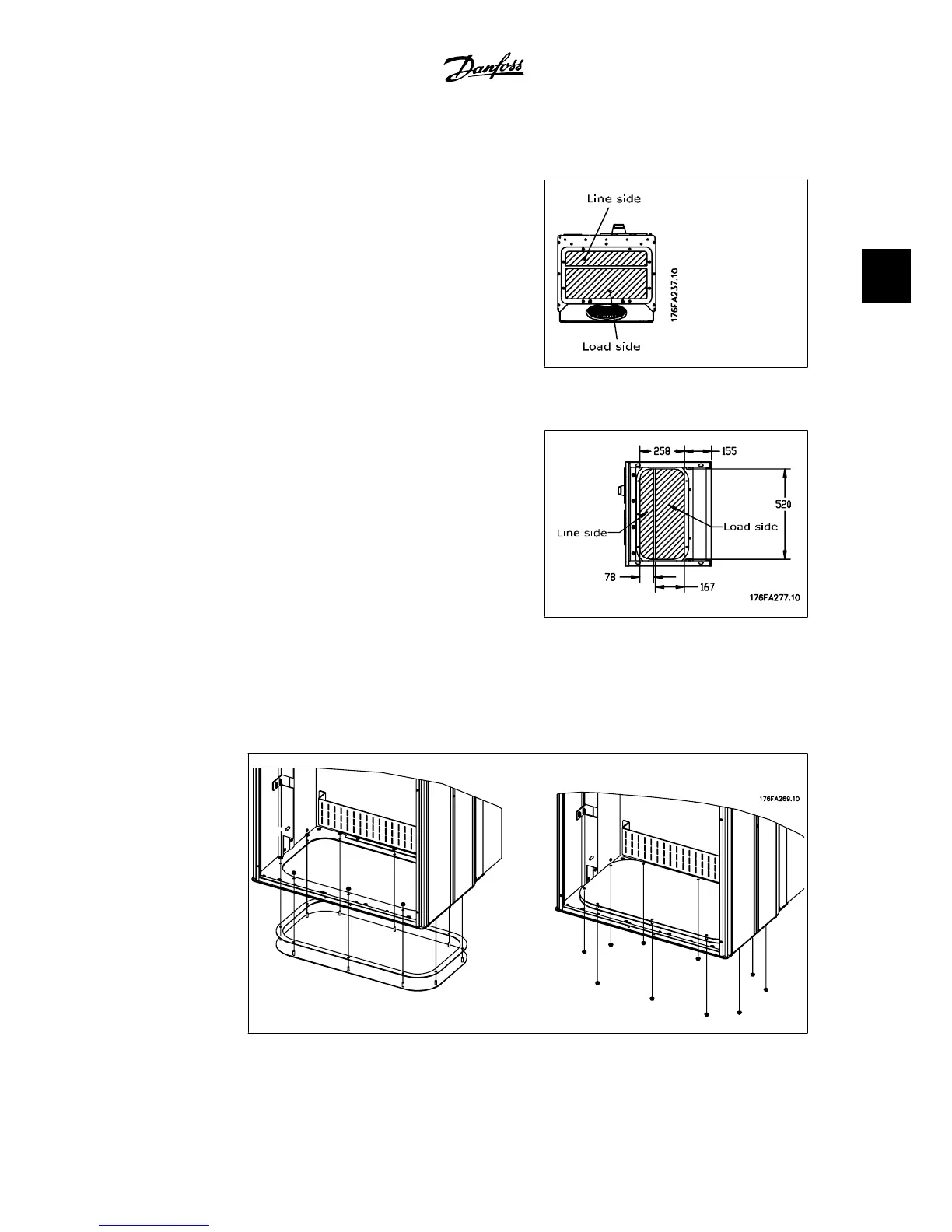
Cables are connected through the gland plate
from the bottom. Remove the plate and plan
where to place the entry for the glands or
conduits. Prepare holes in the marked area on
the drawing.
The gland plate must be fitted to the adjust-
able frequency drive to ensure the specified
protection degree, as well as ensuring proper
cooling of the unit. If the gland plate is not
mounted, it may trip the unit.
3.25: Cable entry viewed from the bottom of the
adjustable frequency drive - Enclosure D1 and D2.
3.26: Cable entry seen from the bottom of the
adjustable frequency drive - Enclosure E1.
The bottom plate of the E1 enclosure can be mounted from either in or outside of the enclosure,
allowing flexibility in the installation process, i.e., if mounted from the bottom, the glands and
cables can be mounted before the adjustable frequency drive is placed on the pedestal.
3.27: Mounting of bottom plate, E1 enclosure.
VLT
®
Automation Drive FC 300
Instruction Manual High Power
3. How to Install
MG.33.U1.22 - VLT
®
is a registered Danfoss trademark.
35
3
 Loading...


