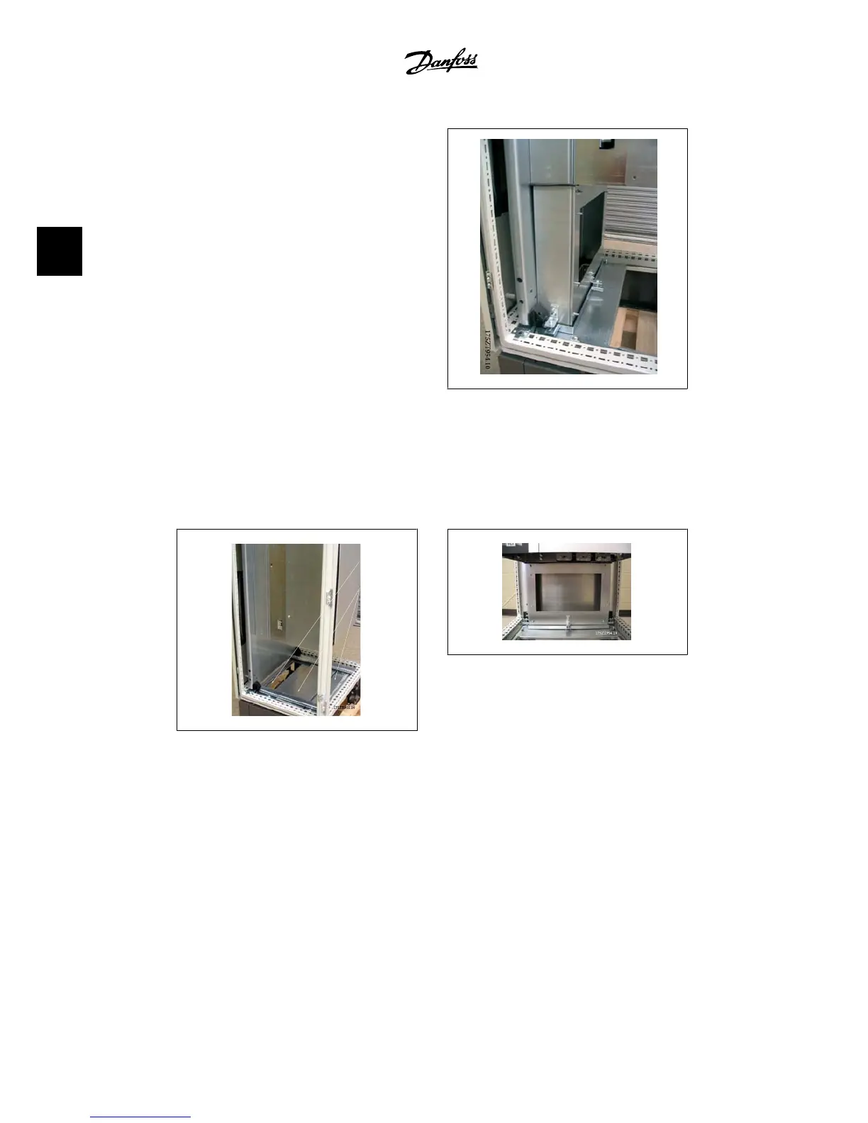
The duct assembly is used to mark the bottom
cut-out. Temporarily install the bottom duct
work as shown to the right. Use the inside of
the duct work to mark the bottom of the en-
closure for the opening.
3.54: Temporarily install the duct work to mark
the cut-out on the gland.
The cut-out is made on the innermost gland
plate. The remaining two gland plates must be
removed for the installation of the bottom
duct assembly.
3.55: Enclosure bottom cut-out
3.56: Bottom duct work installed
The bottom duct work is rotated into place as shown. The bottom ductwork is a tight fit by design.
The upper part of the duct fits under the bottom duct adapter and requires a tight fit, which, with
the gasket material, maintains the IP 54 and UL and NEMA 12 rating.
3. How to Install
VLT
®
Automation Drive FC 300
Instruction Manual High Power
44
MG.33.U1.22 - VLT
®
is a registered Danfoss trademark.
3
 Loading...


