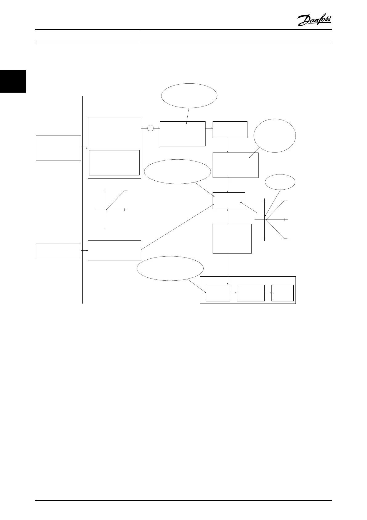
Case 1: Positive reference with dead band, digital input to trigger reverse
Illustration 2.10 shows how reference input with limits inside Min to Max limits clamps.
20
1
10
V
V
20
1
10
-20
130BD454.10
+
Analog input 53
Low reference 0 Hz
High reference 20 Hz
Low voltage 1 V
High voltage 10 V
Ext. source 1
Range:
0.0% (0 Hz)
100.0% (20 Hz)
100.0% (20 Hz)
Ext. reference
Range:
0.0% (0 Hz)
20 Hz 10V
Ext. Reference
Absolute
0 Hz 1 V
Reference
algorithm
Reference
100.0% (20 Hz)
0.0% (0 Hz)
Range:
Limited to:
0%- +100%
(0 Hz- +20 Hz)
Limited to: -200%- +200%
(-40 Hz- +40 Hz)
Reference is scaled
according to min
max reference giving a
speed.!!!
Scale to
speed
+20 Hz
-20 Hz
Range:
Speed
setpoint
Motor
control
Range:
-8 Hz
+8 Hz
Motor
Digital input 19
Low No reversing
High Reversing
Limits Speed Setpoint
according to min max speed.!!!
Motor PID
Hz
Hz
Dead band
Digital input
General Reference
parameters:
Reference Range: Min - Max
Minimum Reference: 0 Hz (0,0%)
Maximum Reference: 20 Hz (100,0%)
General Motor
parameters:
Motor speed direction:Both directions
Motor speed Low limit: 0 Hz
Motor speed high limit: 8 Hz
Illustration 2.10 Clamping of Reference Input with Limits inside Min to Max
Product Overview
VLT
®
AutomationDrive FC 360 Design Guide
22 MG06B202 - VLT
®
is a registered Danfoss trademark
22
 Loading...


