3.7.4 Wiring Procedures
Wiring procedure for enclosure sizes A1–A3
1. Mount the eldbus connector on the eldbus
option (terminals 62, 63, 66, and 67). For top
cable entry, mount the supplied EMC bracket on
top of the frequency converter with 2 screws.
2. Prepare the eldbus cable by stripping a section
of the cable insulation, so that the cable screen is
in contact with the EMC bracket. Keep the
unshielded wire as short as possible. For cable
specications, refer to chapter 3.7.2 Cable Speci-
cations. For eldbus cable requirements, see
chapter 3.7.3 Bus Segment Requirements.
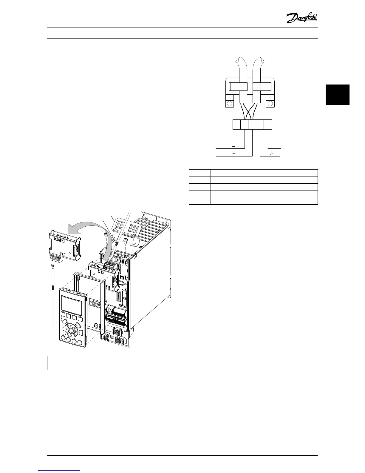
3. Connect the eldbus cable wires to the terminals
according to the colour code of the wires, see
Illustration 3.10.
4. To establish mechanical xation and electrical
contact between cable screen and ground,
position the stripped cable between the spring
loaded metal clamps.
62 RxD/TxD-P red cable
63 RxD/TxD-N green cable
66 and 67 5 V DC supply, available for external termination
CS Control select, 5 V DC indicates transmission from the
eldbus option
Illustration 3.10 Fieldbus Cable Terminal Connections
Installation Installation Guide
MG33C602 Danfoss A/S © 07/2015 All rights reserved. 11
3 3

 Loading...


