Wiring procedure for enclosure sizes A4–A5, B1–B4, and
C1–C4
1. Push the cable through cable glands.
2. Mount the eldbus connector on the eldbus
option (terminals 62, 63, 66, and 67).
3. Prepare the eldbus cable by stripping a section
of the cable insulation. Keep the unshielded wire
as short as possible. For cable specications, refer
to chapter 3.7.2 Cable Specications. For eldbus
cable requirements, see chapter 3.7.3 Bus Segment
Requirements.
4. Connect the eldbus cable wires to the terminals
according to the colour code of the wires, see
Illustration 3.10.
5. Fix the cable screen to the metal base plate using
cable clamp or cable tie, see Illustration 3.11.
6. Tighten cable glands securely.
Illustration 3.11 Wiring for Enclosure Sizes A4–A5, B1–B4, and
C1–C4
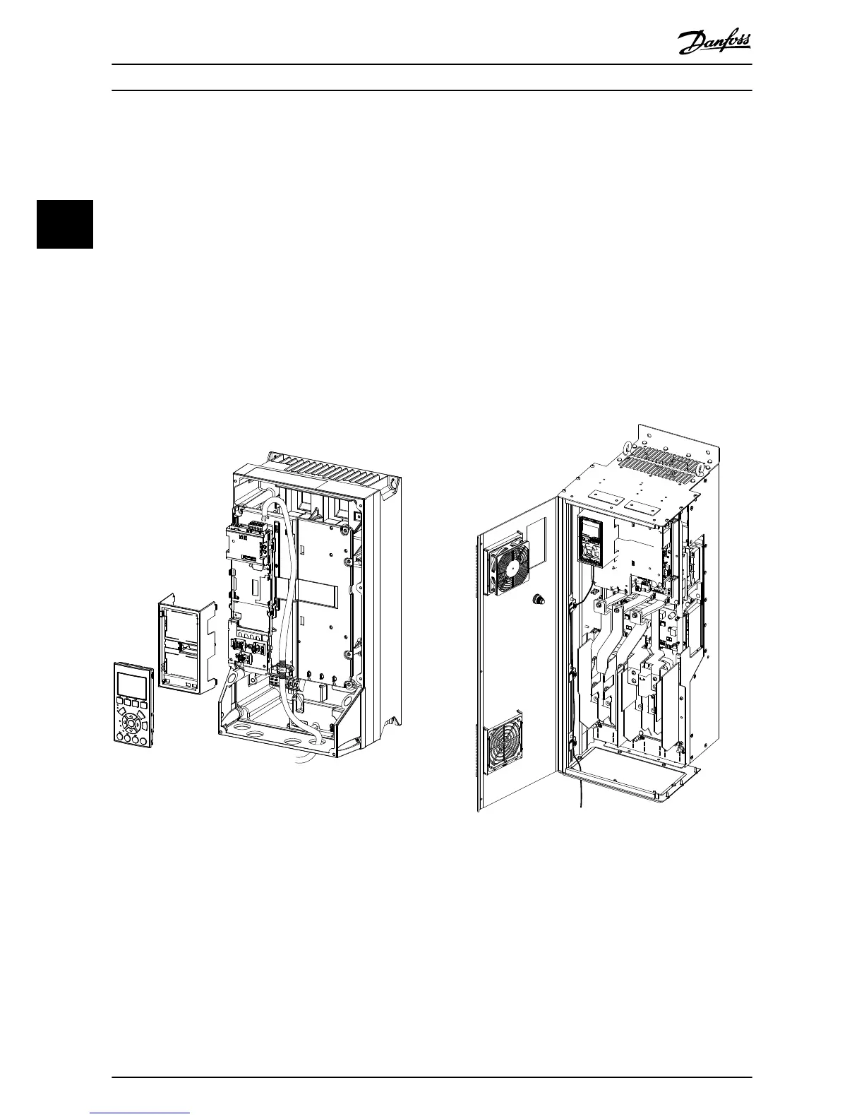
Wiring procedure for enclosure sizes D, E, and F
1. Mount the eldbus connector on the eldbus
option (terminals 62, 63, 66, and 67).
2. Prepare the eldbus cable by stripping a section
of the cable insulation. Keep unshielded wire as
short as possible. For cable specications, refer to
chapter 3.7.2 Cable Specications. For eldbus
cable requirements, see chapter 3.7.3 Bus Segment
Requirements.
3. Connect the eldbus cable wires to the terminals
according to the colour code of the wires, see
Illustration 3.10.
4. Fix the cable screen to the metal base plate using
cable clamp or cable tie, see Illustration 3.12.
5. Tie down the cable and route it with other
control wires inside the unit, see Illustration 3.12.
Illustration 3.12 Wiring for Enclosure Sizes D, E, and F
Installation
VLT
®
PROFIBUS DP MCA 101
12 Danfoss A/S © 07/2015 All rights reserved. MG33C602
33

 Loading...


