Technical Specifications
270 QuickScan™ I QD24XX/QBT24XX/QM24XX
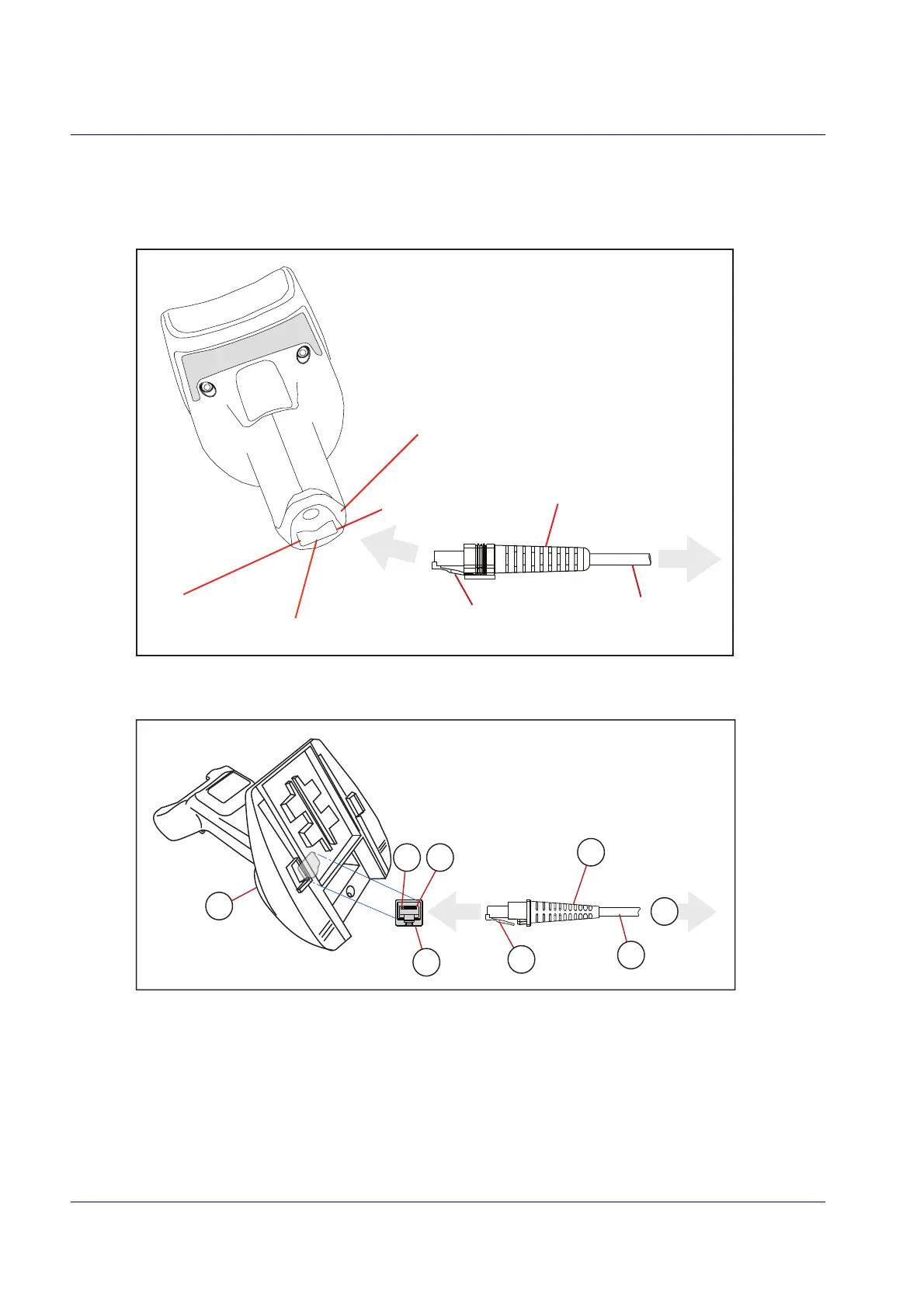
Standard Cable Pinouts
Figure 14, Figure 15 and Table 47 provide standard pinout information for the interface cable.
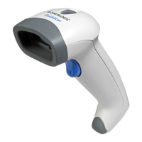
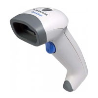
Figure 14. Standard Cable Pinouts: Handheld
Pin 10
Cable Clip (Latch)
To Host
Cable
Cable Strain Relief
Bottom of Scanner
Interface Cable Port
Pin 1
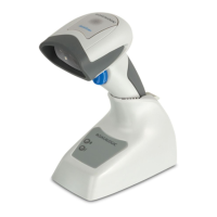
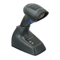
Figure 15. Standard Cable Pinouts: Base Station
The signal descriptions in Table 47 apply to the connector on the reader and are for reference
only.
 Loading...