Service Manual
14
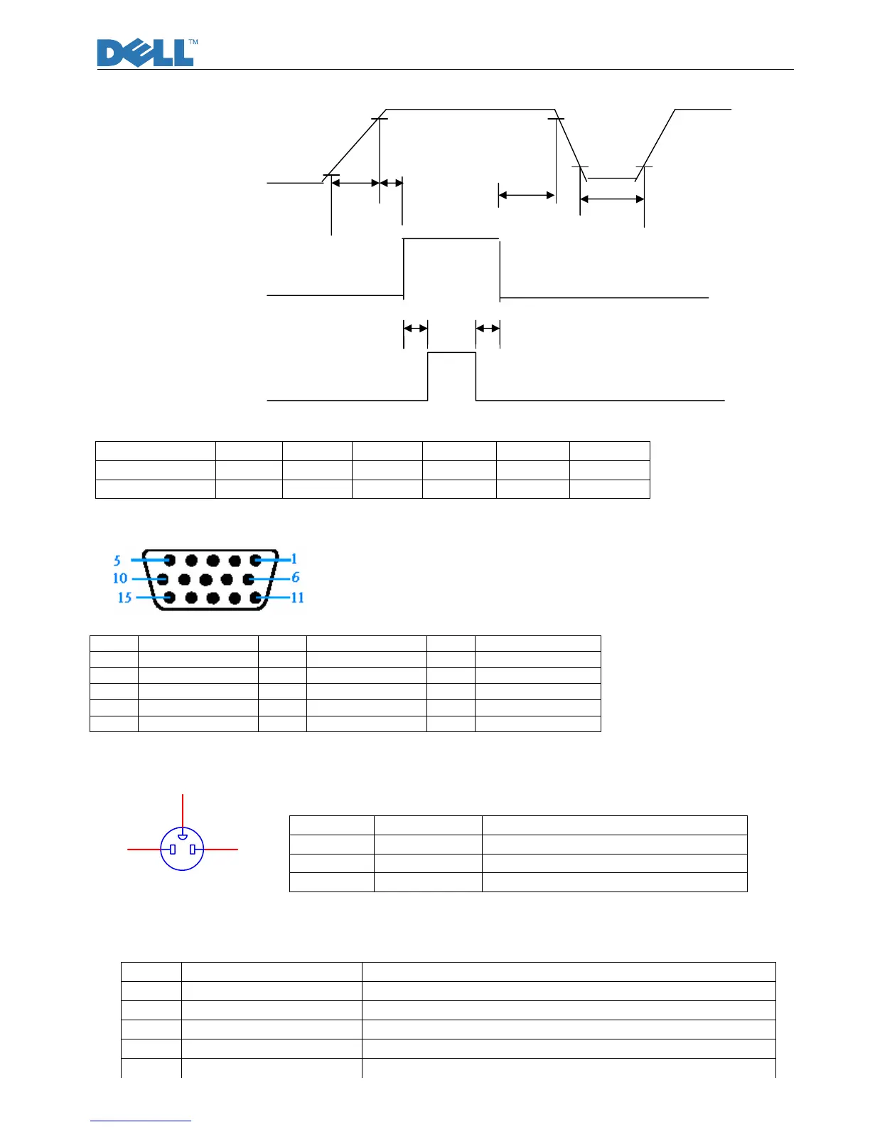
Power supply for panel+5V V
DD
90% 90%
10%
0V 10%
T1 T2
T3 T4
Signals Valid data
(Digital RGB, HS, VS, DE, CLOCK)
0V
T5 T6
Power supply for backlight
T1 (ms) T2 (ms) T3 (ms) T4 (ms) T5 (ms) T6 (ms)
SPEC (HSD) 0.5~10 0~50 0~50 >200 >200 >200
SPEC (LPL) 0.5~10 0.01~50 0.01~50 >500 >500 >200
5. D-SUB Connector Pin Assignment
6. AC input connector Pin Assignment
Pin Symbol Description
1 Line
AC Line(Vin=100 to 240 Vrms,50/60Hz)
2 GND GND
3 Neutral
AC Line(Vin=100 to 240 Vrms,50/60Hz)
7. Inner Connector Pin Assignment
7.1 CN103 (Connect M/B to Panel,)
Pin Symbol Description
1 Panel_Vcc Panel power supply (typ.5.0V)
2 Panel_Vcc Panel power supply (typ. 5.0V)
3 Panel_Vcc Panel power supply (typ. 5.0V)
4 NC
5 NC
Pin Symbol Pin Symbol Pin Symbol
1 Red 6 Red_GND 11 GND
2 Green 7 Green_GND 12 DDC_SDA
3 Blue 8 Blue_GND 13 Hsync
4 GND 9 PC+5V 14 Vsync
5 Cable Detect 10 GND 15 DDC_SCL
CN850
1 3
2
 Loading...