Service Manual
5
Chapter 3- CIRCUIT THEORY
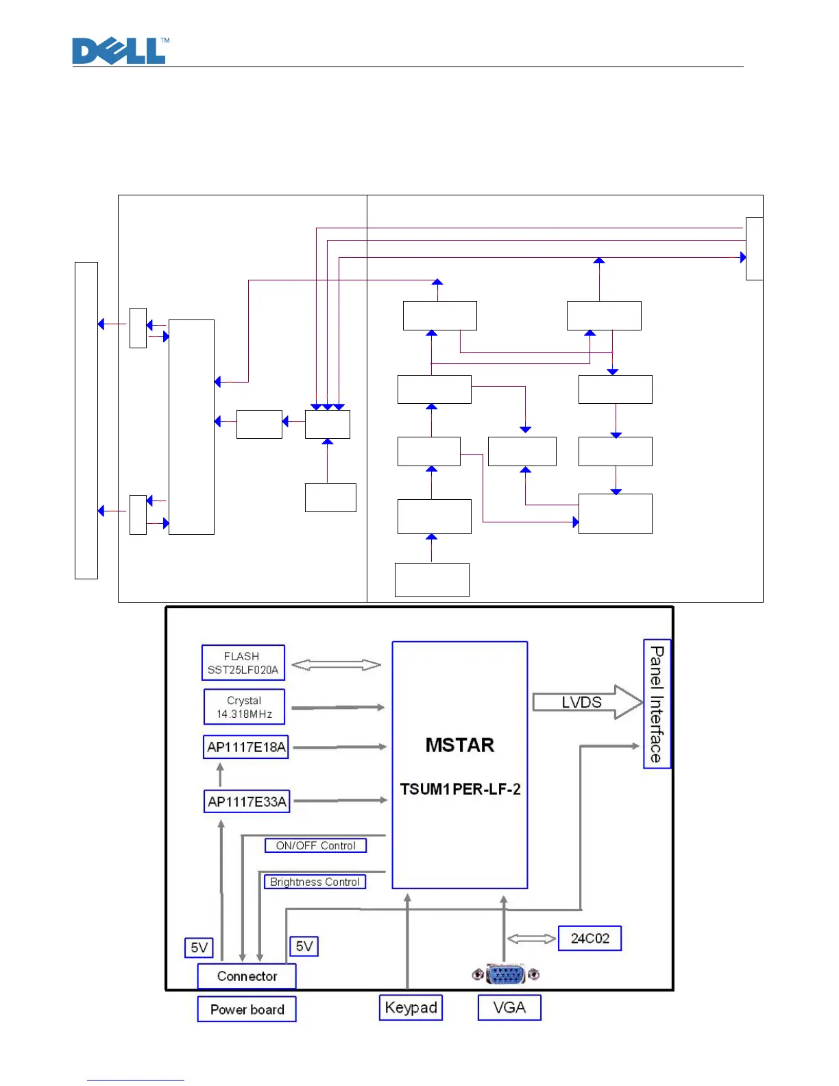
Block Diagram
There are 2pcs PCBA in this monitor, one is power& inverter board which is a single layer board,
and one is interface board&keypad which is OSD control. The system function block diagram as
below
This PWA is included switching power supplier, inverter for CCFL and interface board.(fig.1)
Power
Transformer
MOSFET
Photocoupler
+5V DC output
Snubber
&Schottky
Feedback
Control
Feedback
and OVP
PWM Control IC
LD7575
+12V DC output
2
1
ON/OFF Control
INL837
To Panel CCFL
Lamp2
Snubber
&Schottky
Power
MOSFET
Rectifier&
Filter
Circuit
AC Input
90V~264V
Brightness Control
+5V DC
To IF Board
+5V DC
AC Line Filter
Lamp1
Inverter
Transformer
Fig.1
 Loading...