Steps
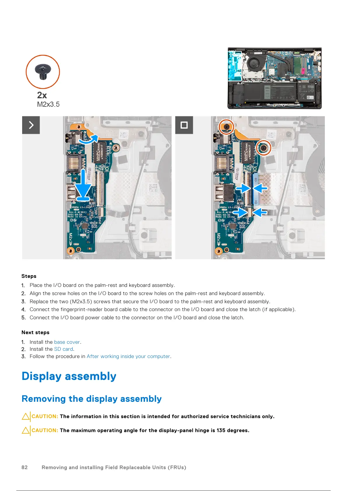
1. Place the I/O board on the palm-rest and keyboard assembly.
2. Align the screw holes on the I/O board to the screw holes on the palm-rest and keyboard assembly.
3. Replace the two (M2x3.5) screws that secure the I/O board to the palm-rest and keyboard assembly.
4. Connect the fingerprint-reader board cable to the connector on the I/O board and close the latch (if applicable).
5. Connect the I/O board power cable to the connector on the I/O board and close the latch.
Next steps
1. Install the base cover.
2. Install the SD card.
3. Follow the procedure in After working inside your computer.
Display assembly
Removing the display assembly
CAUTION: The information in this section is intended for authorized service technicians only.
CAUTION: The maximum operating angle for the display-panel hinge is 135 degrees.
82 Removing and installing Field Replaceable Units (FRUs)
83 / 156 82 / 154 83 / 156
 Loading...