Installing System Components 101
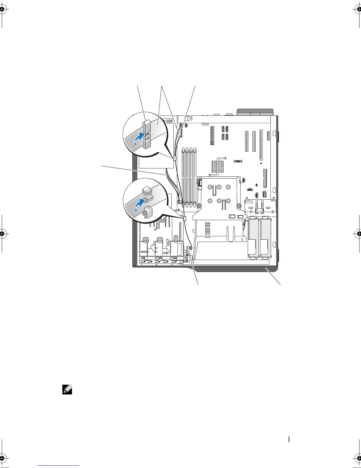
Figure 3-31. Cabling the I/O Panel Assembly
4
Replace the large processor cooling fan. See "Replacing the Cooling Fans"
on page 87.
5
Replace the heat sink and shroud assembly. See "Replacing the Processor"
on page 83.
NOTE: To prevent damaging the processor, clean the heat sink to remove any
thermal grease and then apply fresh thermal grease to the processor before
installing the heat sink.
1 I/O panel connector 2 front drive bezel
3 I/O panel assembly 4 4-pin power cable to system board
5 cable clip on power supply 6 I/O panel ribbon cable
book.book Page 101 Wednesday, June 24, 2009 8:21 AM
 Loading...