Chapter 6 Control Mode of Operation ASDA-A2
6-56 Revision February, 2017
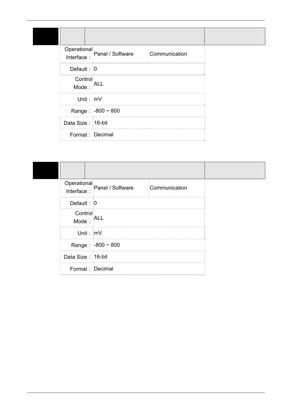
P4-20 DOF1
Offset Adjustment Value of Analog Monitor
Output (Ch1)
Address: 0428H
0429H
Operational
Interface:
Panel / Software Communication
Related Section:
6.4.4
Default:
0
Control
Mode:
ALL
Unit:
mV
Range:
-800 ~ 800
Data Size:
16-bit
Format:
Decimal
Settings:
Offset adjustment value (cannot reset)
P4-21 DOF2
Offset Adjustment Value of Analog Monitor
Output (Ch2)
Address: 042AH
042BH
Operational
Interface:
Panel / Software Communication
Related Section:
6.4.4
Default:
0
Control
Mode:
ALL
Unit:
mV
Range:
-800 ~ 800
Data Size:
16-bit
Format:
Decimal
Settings:
Offset adjustment value (cannot reset)
For example, if users desire to observe the voltage signal in channel 1 and set this channel for
observing the pulse command frequency, when the pulse command frequency 2.25M corresponds
to 8V output voltage, users need to adjust the monitor output proportion of P1-04 to 50 (= 2.25M/
Max. input frequency). Other related settings include P0-03 (X= 3) and P1-03 (The polarity setting
range of monitor analog output is between 0 and 3, and it can set positive/negative polarity output).
Generally speaking, the output voltage of Ch1 is V
1
; the pulse command frequency is (Max. input
frequency × V
1
/8) × P1-04/100.
Because of the offset value, the zero voltage level of analog monitor output does not match to the
zero point of the setting. This can be improved via the setting of offset adjustment value of analog
 Loading...


