5.3 DC Connection (from PV Array)
The maximum open circuit voltage of the PV Array must not exceed
500Vdc(H2.5) / 600Vdc (H3 / H3A / H4A / H5A).
CAUTION !
WARNING !
• When undertaking DC wiring, please ensure the correct polarities are connected.
• When undertaking DC wiring, please ensure that the DC isolator switch on the
PV array is OFF.
The isolator installed between the PV Array and inverter must meet the rating
of voltage higher than this device’s maximum input voltage.
NOTE
The RPI range of PV inverters uses genuine Multi-Contact® MC4 connectors.
5.3.1 Asymmetrical Loading
5.3.1.1 DC connector of
H3A / H4A / H5A_220 / H5A_221
The inverters (H3A / H4A / H5A) operate using two separate MPP trackers that can
handle both symmetrical and asymmetrical loads to allow for optimum adjustment.
This allows for the requirements of complex PV system designs to be fulfilled.
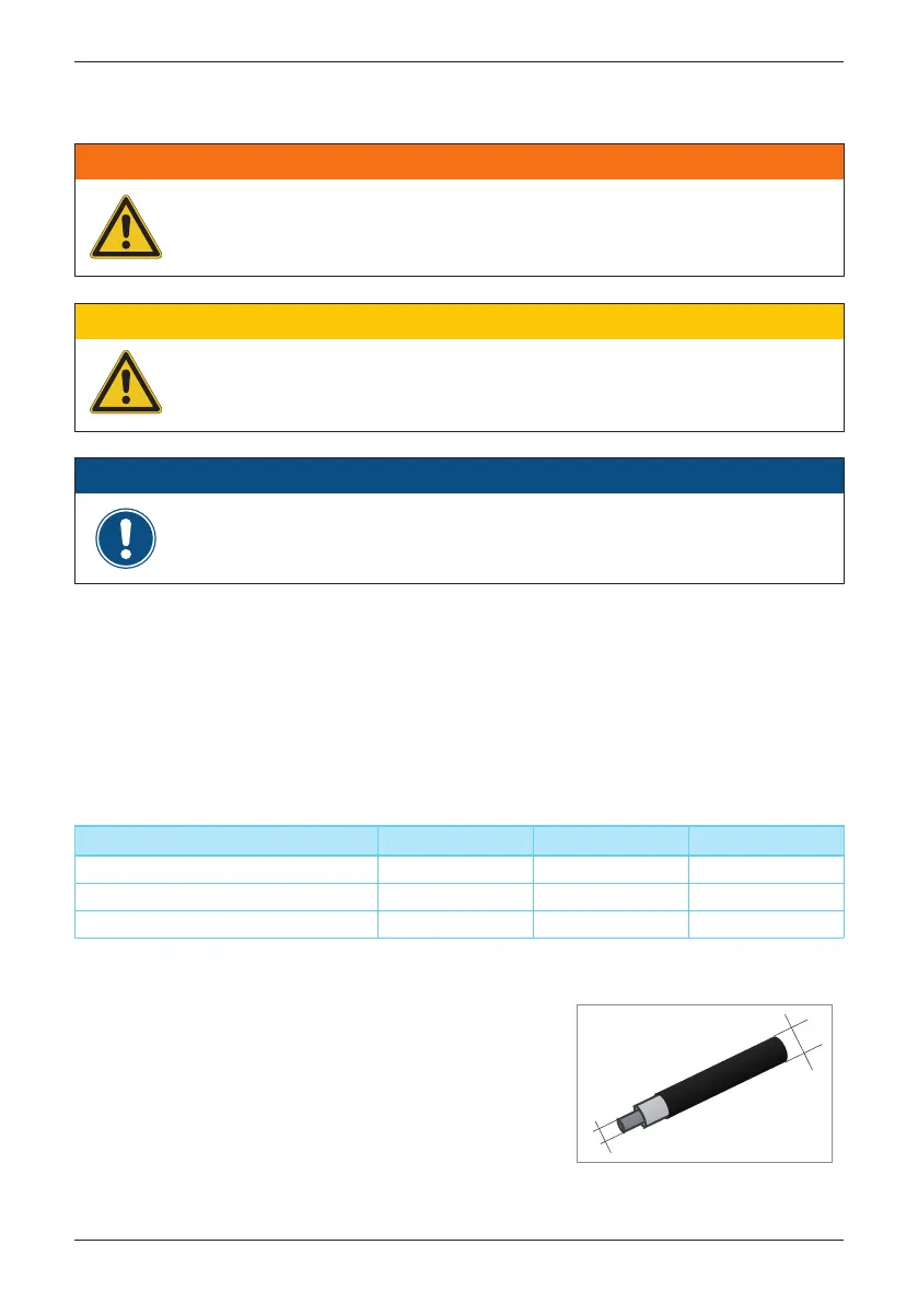
DC plugs and DC cables
The DC plugs for all DC connections are provided
along with the inverter.
If you want to order more or need a different
size, see the information in the following table.
MPP range with Max. power H3A
Symmetrical load 180~500V
Asymmetrical load 290~500V
Max. ratio for asymmetrical load 100/0% ; 0/100%
H4A
240~500V
380~500V
100/0% ; 0/100%
H5A
240~500V
430~500V
94/6% ; 6/94%
a
b
Wiring
21
 Loading...