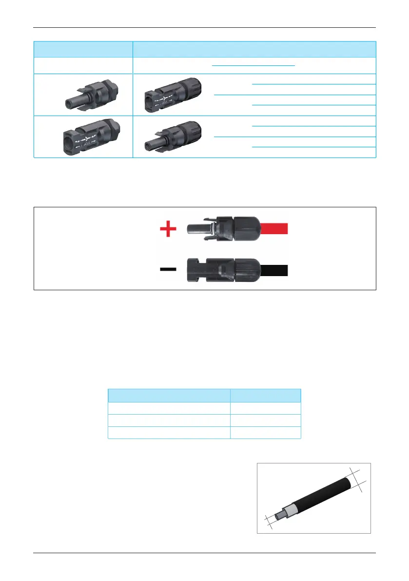
DC wiring polarities have two components, Plus and Minus, which are shown in
Figure 5-4. The connection shall conform to the indication marked on inverter.
Table 5-3 : MC4 connectors
Figure 5-4 : DC Wiring illustration of H3A / H4A / H5A_220 / H5A_221
PV-KBT 4/6 Ⅱ
PV-KST 4/6 Ⅱ
DC connectors on
the inverter
DC plugs for DC cable
a b
Multi-Contact
mm
2
mm
DC–
1,5/2,5
3–6 32.0010P0001-UR
5,5–9 32.0012P0001-UR
4/6
3–6 32.0014P0001-UR
5,5–9 32.0016P0001-UR
DC+
1,5/2,5
3–6 32.0011P0001-UR
5,5–9 32.0013P0001-UR
4/6
3–6 32.0015P0001-UR
5,5–9 32.0017P0001-UR
5.3.1.2 DC connector of H5A_222
The RPI range of PV inverters uses genuine Amphenol H4 connectors.
The inverter (H5A_222) operate using two separate MPP trackers that can
handle both symmetrical and asymmetrical loads to allow for optimum adjustment.
This allows for the requirements of complex PV system designs to be fulfilled.
DC plugs and DC cables
The DC plugs for all DC connections are provided
along with the inverter.
If you want to order more or need a different
size, see the information in the following table.
MPP range with Max. power
Symmetrical load
Asymmetrical load
Max. ratio for asymmetrical load
H5A
_222
240~500V
430~500V
94/6% ; 6/94%
a
b
Wiring
22
 Loading...