16
DC wiring polarities are divided into Plus and Minus, which are shown in
Figure 5-4. The connection shall conform to the indication marked on inverter.
Figure 5-4: DC Wiring illustration
5.4 Communication Module
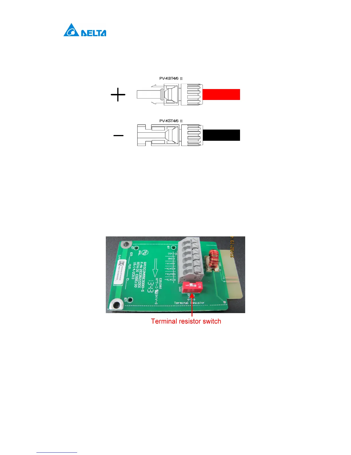
The Communication Module enables communication between the unit and a
computer and provides 2 RS-485 ports. When using this module, the first step
is to take off the cover located at the bottom right of inverter and pull out the
RS485 socket as shown in Figure 5-5.
Figure 5-5: Communication module
5.4.1 RS-485 Connection
The pin definition of RS-485 shown in Table 5-5 and protocol settings are listed
in Table 5-6. Installer must switch the terminal resistor switch to ON when only
a single inverter is installed. The wiring of multi-inverter is shown in Figure 5-6.
The terminal resistor switch of the first and last inverters should be switched
ON, and the others OFF.
 Loading...


