20
• fixed power factor cosφ (VDE-AR-N 4105 ,CEI 0-21)
• displacement factor/active power characteristic curve cosφ(p) (VDE-AR-N
4105 ,CEI 0-21)
• fixed reactive power in Var.(CEI 0-21)
• reactive power/voltage characteristic Q(U). (CEI 0-21)
6.2.1 Fixed Power Factor cosφ (VDE-AR-N 4105,CEI 0-21)
Users can set power factor from Cap 0.8 to Ind 0.8 (inverter would stop
reactive power control if output power is below 20% rated power). \
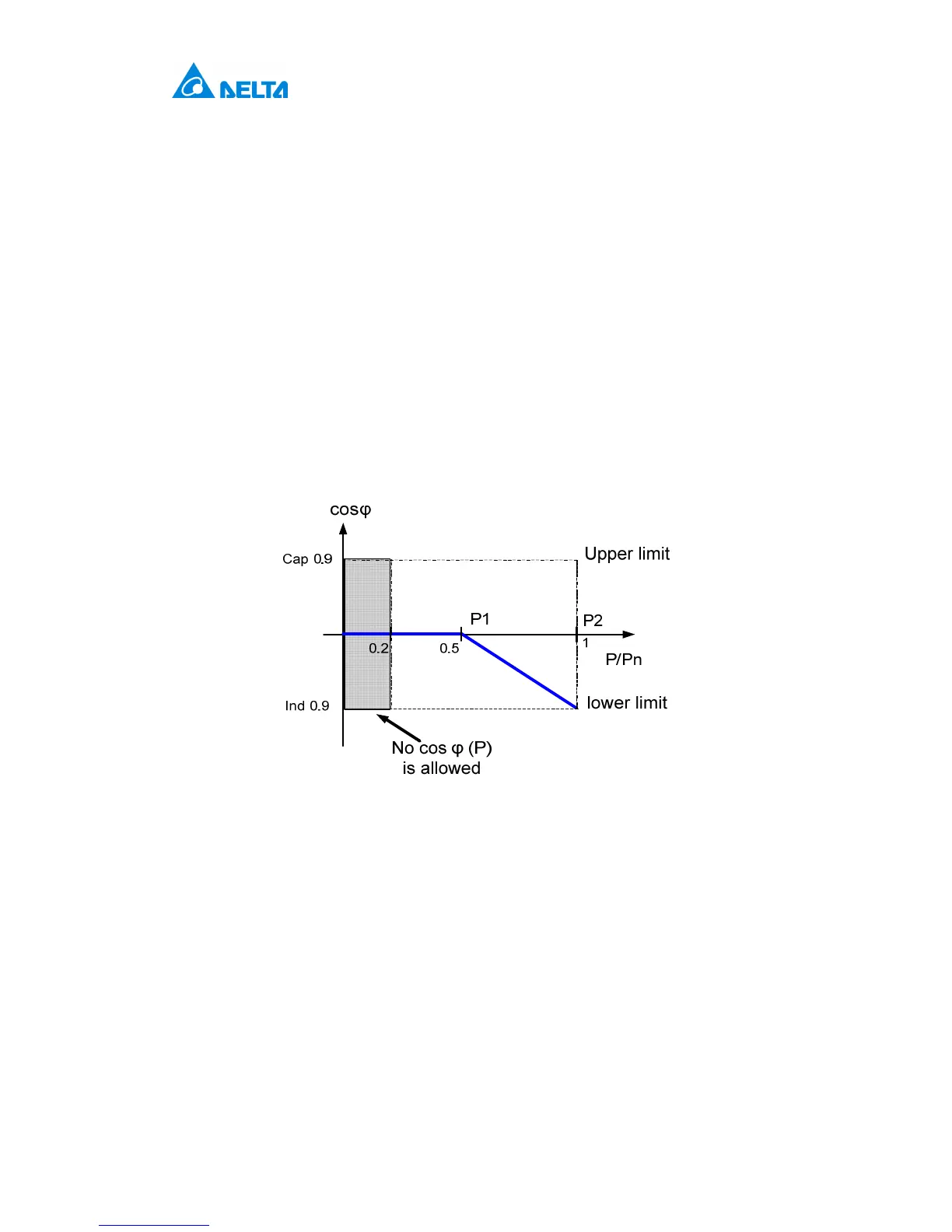
6.2.2 cosφ(P) (VDE-AR-N 4105,CEI 0-21)
Once user enables this method, inverter will deliver reactive power according
to output active power at that moment. Figure 6-2 is an example.
Figure 6-2: cosφ(P) characteristic
6.2.3 Fixed Reactive Power InVAR(CEI 0-21)
Once user enables this method, inverter will deliver reactive power (ie. Q)
consistent with that of the fixed reactive power setting. The setting range is
from Cap 48.4% to Ind 48.4%.
6.2.4 Reactive Power/ Voltage Characteristic Q(U)(CEI
0-21)
Once user enables this method, user can set Q vs Grid voltage operation
curve as in figure 6-3 below.
 Loading...


