23
DC wiring polarity is divided into positive and negative, which is shown as in
figure 5-5. The connection shall be coherent with the indication marked on
inverter.
Figure 5-5 DC Wiring illustration
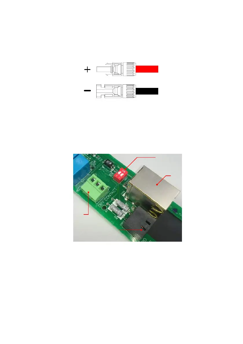
5.4 Communication Module Connections
The Communication Module support the functions of communication with
computer, also provides 2 EPO input signals and 1 dry contact.
Terminal Resistor
Dry contact
(3A / 28V)
EPO
(Emergency Power off)
RS-485
Figure 5-6 Communication module
5.4.1 RS-485 Connection
The pin definition of RS-485 is shown as in table 5-5. Installers should switch ON
the terminal resistor when single inverter is installed. The wiring of multi-inverter
connection is shown as figure 5-7. Installers should switch ON terminal resister
at the first and last devices of the RS485 chain as Figure 5-7. The other terminal
resisters should be switch OFF. Please refer to table 5-7 for the terminal resister
setting.
 Loading...


