EasyManuals Logo
Home>Delta>Inverter>RPI-M20A

Delta RPI-M20A Manual

Delta RPI-M20A
63 pages
To Next Page IconTo Next Page
To Previous Page IconTo Previous Page
Page #29 background imageLoading...
Page #29 background image
28
6.2.2 Active Factor cosφ(P)
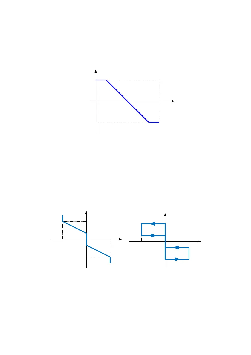
Once user enables this method, inverter will deliver reactive current according to
output active power at that moment. The below figure is an example. Please refer
to 7.2.6.4.4 cosφ(P) for the settings procedure.
Cap 0.85
Ind 0.85
P/Pn
1
cosφ
Figure 6-2 cosφ(P) characteristic
6.2.3 Fixed Reactive Power
Enables this method, inverter will deliver reactive power (ie. Q) according to the
fixed reactive power setting. The setting range is from Cap 53% to Ind 53%.
6.2.4 Reactive Power / Voltage Characteristic Q(U)
After selecting “Q(U) control”, User can adjust Q vs. Grid voltage operation
curves as below. The left curve is “Curve A”, the right curve is “Curve B”.
V
1s
V
2s
V
1i
V
2i
Q
i limit
Q
s limit
V
V
1s
V
2s
V
1i
V
2i
Q
i limit
Q
s limit
V
Q
CurveA CurveB
Figure 6-3 Q(U) characteristic.

Table of Contents

Other manuals for Delta RPI-M20A

Questions and Answers:

Question and Answer IconNeed help?

Do you have a question about the Delta RPI-M20A and is the answer not in the manual?

Delta RPI-M20A Specifications

General IconGeneral
BrandDelta
ModelRPI-M20A
CategoryInverter
LanguageEnglish

Related product manuals