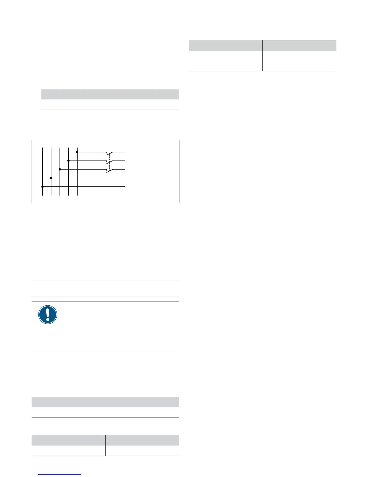
N
L1
L2
L3
PE
to the
inverter
Residual current circuit breaker
Due to its design, the inverter cannot supply the grid with DC
residual current. This means that the inverter meets the require-
ments of DIN VDE 0100-712.
Possible error events were assessed by Delta in accordance with
the current installation standards. The assessments showed that
no hazards arise from operating the inverter in combination with
an upstream, type A residual current circuit breaker (FI circuit
breaker, RCD). There is no need to use a type B residual current
circuit breaker.
Minimum tripping current of the type A residual
current circuit breaker
≥100 mA
The required tripping current of the residual cur-
rent circuit breaker depends rst and foremost
on the quality of the solar modules, the size of
the PV system, and the ambient conditions (e.g.
humidity). The tripping current must not, however,
be less than the specied minimum tripping cur-
rent.
Integrated residual current monitoring unit
The integrated, universal current-sensitive residual current moni-
toring unit (RCMU) is certied in accordance with VDE 0126 1-1/
A1:2012-02 §6.6.2.
Permissible grounding systems
Grounding system TN-S TN-C TN-C-S TT IT
Allowed Yes Yes Yes Yes No
Requirements for the grid voltage
3P3W Voltage 3P4W Voltage
L1-L2 400 V
AC
±20 % L1-N 230 V
AC
±20 %
3P3W Voltage 3P4W Voltage
L1-L3 400 V
AC
±20 % L2-N 230 V
AC
±20 %
L2-L3 400 V
AC
±20 % L3-N 230 V
AC
±20 %
Cable requirements
The AC plug provided with the inverter has the following technical
characteristics:
Plug type Amphenol C16-3
Nominal current ≤25 A
Minimum / maximum cable
diameter
11 / 20 mm
Minimum / maximum wire
cross-section
5 / 8 mm
2
Recommended tightening
torque for clamping screws
≥0.7 Nm
The AC plug can only be used with a exible copper cable.
Consider the following factors when calculating the cable diam-
eter:
● Cable material
● Temperature conditions
● Cable length
● Installation type
● Voltage drop
● Loss of power in the cable
► Always follow the installation regulations for AC cables ap-
plicable in your country.
► France: Follow the installation regulations of UTE 15-712-1.
This standard contains the requirements for minimum cable
diameters and for avoiding overheating due to high cur-
rents.
► Germany: Follow the installation regulations of VDE 0100-
712. This standard contains the requirements for minimum
cable diameters and for avoiding overheating due to high
currents.
► Australia/New Zealand: Follow the installation regulations
of AS/NZS 5033:2005. This standard contains the require-
ments for minimum cable diameters and for avoiding over-
heating due to high currents.
Using external grid and system protection
The German standard VDE-AR-N 4105, Section 6.1, requires
external grid and system protection with a coupling switch for PV
system larger than 30 kVA.
Alternatively, VDE-AR-N 4105, Section 6.4.1, allows the use of
an inverter with an internal coupling switch when this switch dis-
connects the inverter from the grid in less than 100 ms.
This inverter satises the requirements of VDE-AR-N 4105, Sec-
tion 6.4.1 when the following rmware is installed: DSP ≥ 1.30 /
RED ≥ 1.20 / COMM ≥ 1.10. External grid and system protection
is not necessary in this case.
Connecting the mains (AC)
 Loading...