20
Quick installation guide for solar inverters RPI M6A M8A M10A EU V4 EN 5013221703 00 2017-11-16
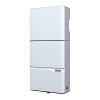
Connecting the digital inputs, dry con-
tacts and external power-off (optional)
1 2 3
4
1 12 V
DC
power supply - GND (plug with screw terminals)
2 12 V
DC
power supply - VCC (plug with screw terminals)
3 Dry contacts (plug with screw terminals)
4 Digital inputs and external power-off (EPO) (RJ45)
Cable and wiring requirements
● Shielded twisted-pair cable with solid conductors (CAT 5 or
CAT 6.
● Cable diameter: 5 mm
● Wire cross-section: 0.25 ... 1.5 mm
2
► Lay the cable with a suitable clearance to the AC and DC
cables to prevent interference in the data connection.
Digital inputs and external power-off (EPO)
To control the active power, an external ripple control receiver
can be connected to the digital inputs.
Pin Short circuit Assigned action
V1 - -
K0 V1 + K0 External power-off (EPO)
K1 V1 + K1 Max. active power 0%
K2 V1 + K2 Max. active power 30%
K3 V1 + K3 Max. active power 60 %
K4 V1 + K4 Max. active power 100%
K5 V1 + K5 Reserved
K6 V1 + K6 Reserved
After commissioning, the relays can be dened as make-contact
or break-contact for the external shutdown on the display.
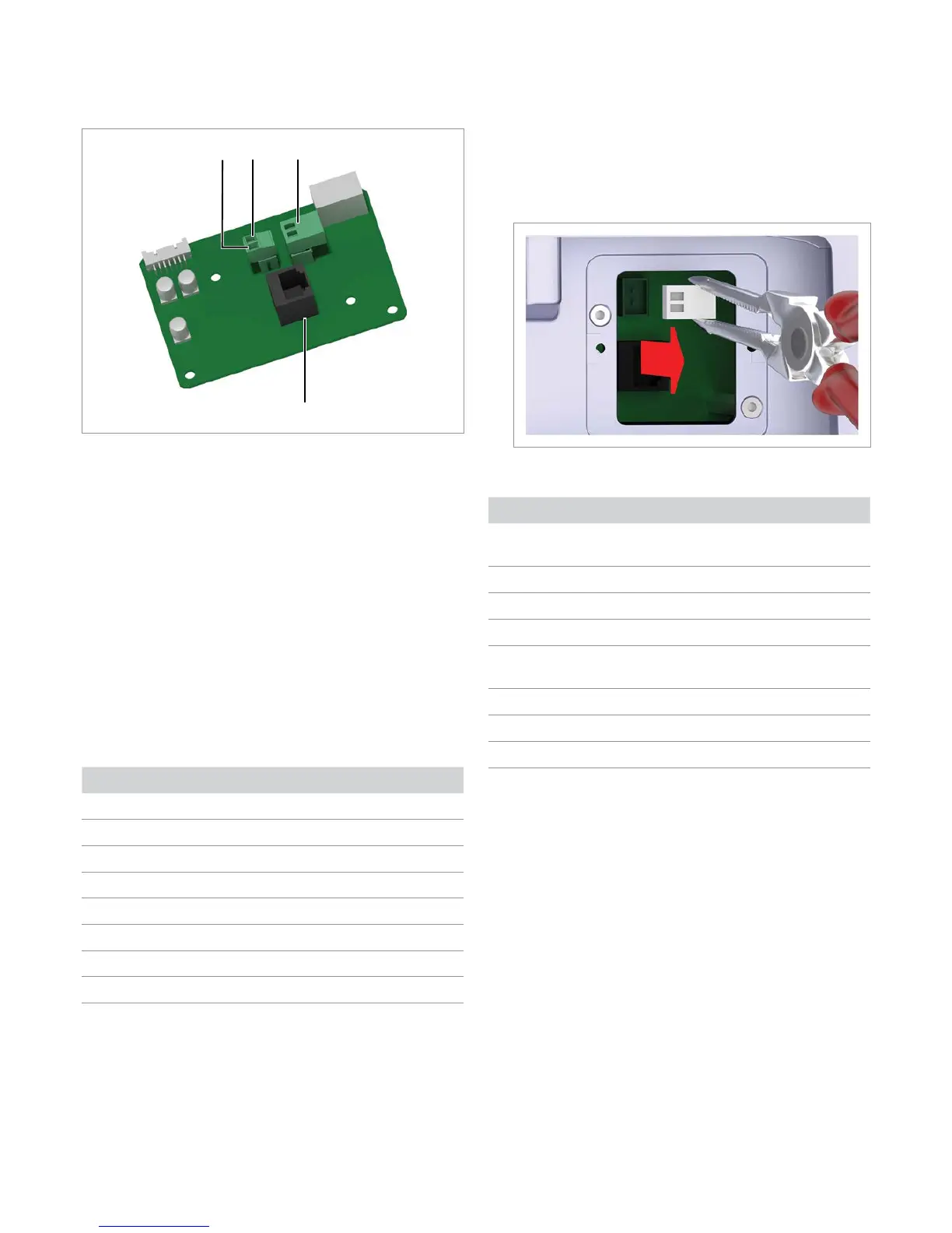
Dry contacts
Both contacts are closed when the inverter feeds electricity into
the grid.
► Carefully pull out the plug for the dry contacts using long-
nose pliers.
After commissioning, an event can be assigned to the dry con-
tacts on the display of the inverter.
Event Description
Disabled
The functions for the dry contacts are
switched off.
On Grid
Inverter is connected to the mains grid.
Fan failure
The fans are defective.
Insulation
Insulation test failed.
Alarm
An error, failure or warning message is
present.
Error
An error message is present.
Fault
A failure message is present.
Warning
A warning message is present.
The default setting is Disabled.
 Loading...