Delta Electric Servo Press - S Series
Installation and Maintenance Instructions
17
4.5 Loading and Unloading Spindle Punch
Recommended punch jig design is provided in this section to facilitate realistic application by users.
4.5.1 AM-ESP-S005-XXXX / AM-ESP-S010-XXXX Standard
Type
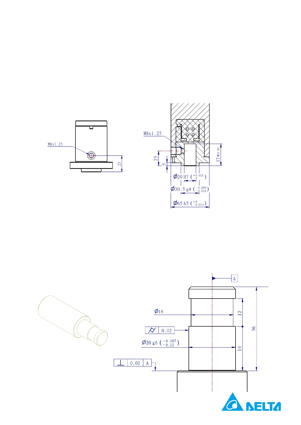
The cross-section of the spindle is shown below. For the punch jig, please use M8 x 1.25 length 8mm
set screws.
Caution: The top of the spindle punch is installed with the load cell. Do not assemble tools in a way
that could result in deviations or impacts.
※ The recommended dimensions of the jig spindle are shown in the figure below. Ø 18, in particular, is
meant to avoid the bur that occurs on the spindle as the jig is removed multiple times and will
accordingly make it impossible to remove the jig out of the spindle.
 Loading...