9
Control Circuit Wiring
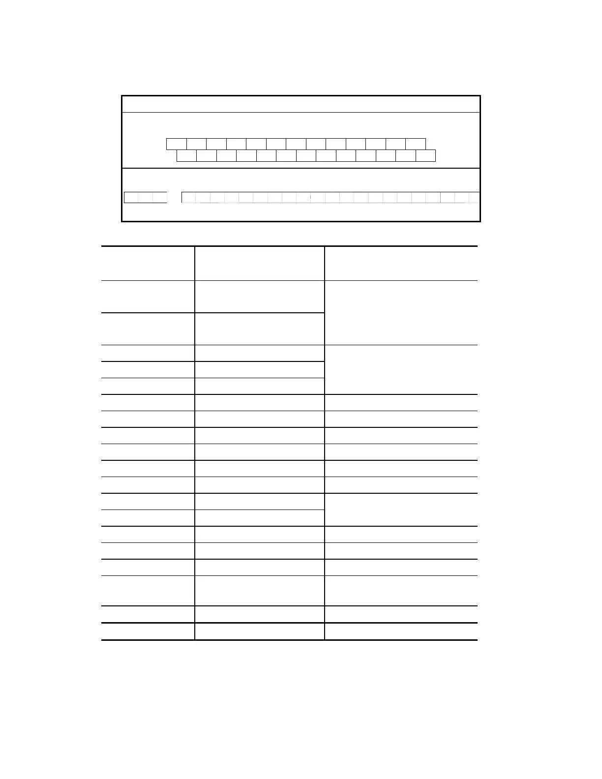
(1) Control terminal block designations
The control leads must be routed separately from the power supply and motor leads.
They must not be fed through the same cable conduit.
Terminal Symbol
220V/440V Class 1∼5HP (AWG: 28 – 14; Torque:4 kgf-cm)
RA
ACI
AVI
+10V
RB RC
MO1
ACMAFM
MCMMO2
MI1
RST
REVFWD
MI2
MI3 DCM
TRGEF SG-SG+DFM
DCM
+EV
220V/440V Class 7.5∼30HP (AWG: 24 – 12; Torque:4 kgf-cm)
RA
ACIAVI
+10VRB RC
MO1 ACM
AFM
MCM
XX
MO2
MI1
RST
REV
FWD
MI2 MI3
DCMTRGEF S
SG+DFM
(2) Control terminal block descriptions
Close Contacts
between Terminals
Terminals Use Function
RA - RC Multi-function indication output
contact
Refer to Chapter 5, Pr.57
RB - RC Multi-function indication output
contact
MI1 - DCM Multi-function input 1
MI2 - DCM Multi-function input 2 Refer to Chapter 5, Pr.39, 40, 41
MI3 - DCM Multi-function input 3
REV - DCM Reverse / Stop “Open”→stop, “Close” → Reverse
FWD - DCM Forward / Stop “Open”→stop, “Close” → Forward
RST - DCM Reset “Close” → Reset
EF - DCM External fault “Close” → External fault
DFM - DCM Digital frequency meter Digital frequency output (0, +10 V)
TRG - DCM Counter trigger input “Open”→“Close”:(counter value)+1
MO1 - MCM Multi-function PHC output 1 Refer to Pr.45, 46
MO2 - MCM Multi-function PHC output 2 (open collector output)
+10V - ACM Power supply for speed setting +10 V (20 mA max. output current)
AVI - ACM Analog voltage input 0 ∼10 V (Max. output freq.) input
ACI - ACM Analog current input 4 ∼20 mA (Max. output freq.) input
AFM - ACM
Analog frequency/current
meter
0 ∼10 V (Max. output freq.) output
SG+ - SG- Serial communication interface RS-485 serial port
+EV - DCM Auxiliary control power source DC 20V ~ 24V (50mA Max.)
Note: Use twisted-shielded or twisted-pair shielded-lead wires for the control signal. It is
recommended to run signal wiring in a separate steel conduit. The shield wire should only be
connected at the drive.
Call 1(800)985-6929 for Sales
Call 1(800)985-6929 for Sales
 Loading...