3
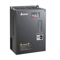
Identification of components and accessories
1
2
3
4
5
6
7
8
9
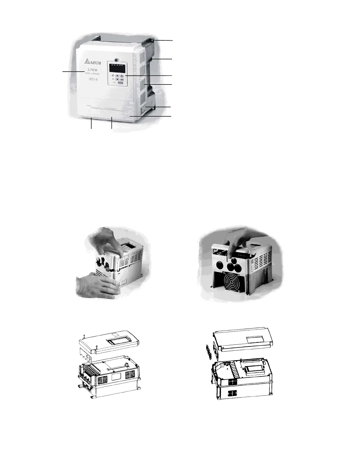
Removing and Installing the Front Cover
Refer to the figure shown below to remove the front cover. To re-install the front cover,
simply reverse the indicated procedures.
♦0.75 - 1.5 KW (1-2HP) ♦2.2 - 3.7 KW (3-5HP)
The front cover snaps on. Pull as The front terminal block cover snaps
shown to remove the front cover. on. Pull as shown to release cover.
♦5.5 - 22.0 KW (7.5-30HP) ♦5.5 - 22.0 KW (7.5-30HP)
1. Mounting screw holes
2. Heat sink
3. Digital keypad
4. Ventilation hole and blind plate
installation position
5. Nameplate label
6. Terminal cover
7. Input / output rating
8. Cooling fan
9. External braking resistor (optional)
Call 1(800)985-6929 for Sales
Call 1(800)985-6929 for Sales
 Loading...