13
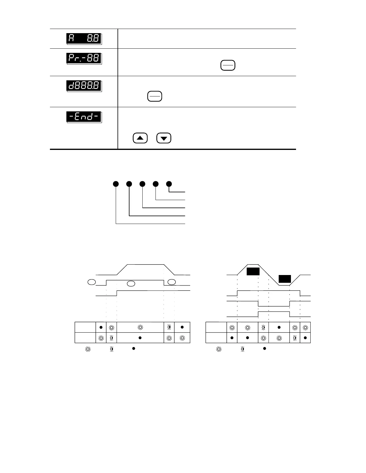
Displays the output current present at terminals U, V, and W
Displays the specified parameter number. The actual parameter
value may be displayed by pressing the
FUNC
DATA
key.
Displays actual value stored within the specified parameter.
Press the
FUNC
DATA
key to store the value of the specified parameter.
The display will read “end” (as shown) for approximately 1 second if
the input has been accepted. After a parameter value has been set,
the new value is automatically stored in memory. To modify an entry,
use
or key.
Explanation of the LED Indicators
REV
FWD
JOG
STOPRUN
Red lamp lights during REV operation.
Red lamp lights during FWD operation.
Red lamp lights during JOG.
Red lamp lights by pressing STOP.
Red lamp lights by pressing RUN.
RUN or STOP lamp indication is
defined by the following operation
FWD or REV lamp changes indication is
defined by the following operation
Inverter output frequency
Frequency command
RUN
LAMP
STOP
LAMP
LIGHT
BLINK
LIGHT OFF
key
STOP
FWD
LAMP
REV
LAMP
FWD
REV
RUN
OUTPUT
FREQ.
REV
FWD
LIGHT
BLINK
LIGHT OFF
key
STOP
key
RUN
Call 1(800)985-6929 for Sales
Call 1(800)985-6929 for Sales
 Loading...