3
VFD-B Series
DELTA ELECTRONICS, INC. ALL RIGHTS RESERVED
3-7
3.3 Terminal Explanations
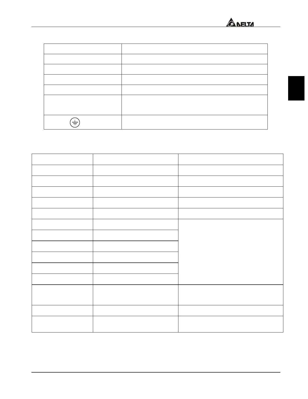
Terminal Symbol Explanation of Terminal Function
R/L1, S/L2, T/L3 AC line input terminals
U/T1, V/T2, W/T3 AC drive output terminals motor connections
+1,+2 Connections for DC Link Reactor (optional)
+2/B1~B2 Connections for Braking Resistor (optional)
+2 ~ -(minus sign)
+2/B1~ -(minus sign)
Connections for External Braking Unit (VFDB series)
Earth Ground
3.4 Control Terminals Explanations
Terminal Symbols Terminal Functions Factory Settings
FWD Forward-Stop command
REV Reverse-Stop command
JOG Jog command
EF External fault
TRG External counter input
MI1
Multi-function Input 1
MI2
Multi-function Input 2
MI3
Multi-function Input 3
MI4
Multi-function Input 4
MI5
Multi-function Input 5
MI6
Multi-function Input 6
Refer to Pr.04-04 to Pr.04-09
Multi-function Input Terminals
DFM
Digital Frequency Meter
(Open Collector Output)
Factory setting 1:1
(Maximum 48VDC, 50mA)
+24V
DC Voltage Source
(+24V, 20mA), used for source mode.
DCM
Digital Signal Common
Used as common for digital inputs
and used for sink mode.
 Loading...