20
AVR-1910/1620/1610/790/590
ADJUSTMENT
Audio Section
Idling Current
Required measurement equipment: DC Voltmeter
1. Preparation
(1) Avoid direct blow from an air conditioner or an electric fan, and adjust the unit at normal room temperature
15 °C ~ 30 °C (59 °F ~ 86 °F).
(2) Presetting
• POWER (Power source switch) OFF
• SPEAKER (Speaker terminal) No load
(Do not connect speaker, dummy resistor, etc.)
2. Adjustment
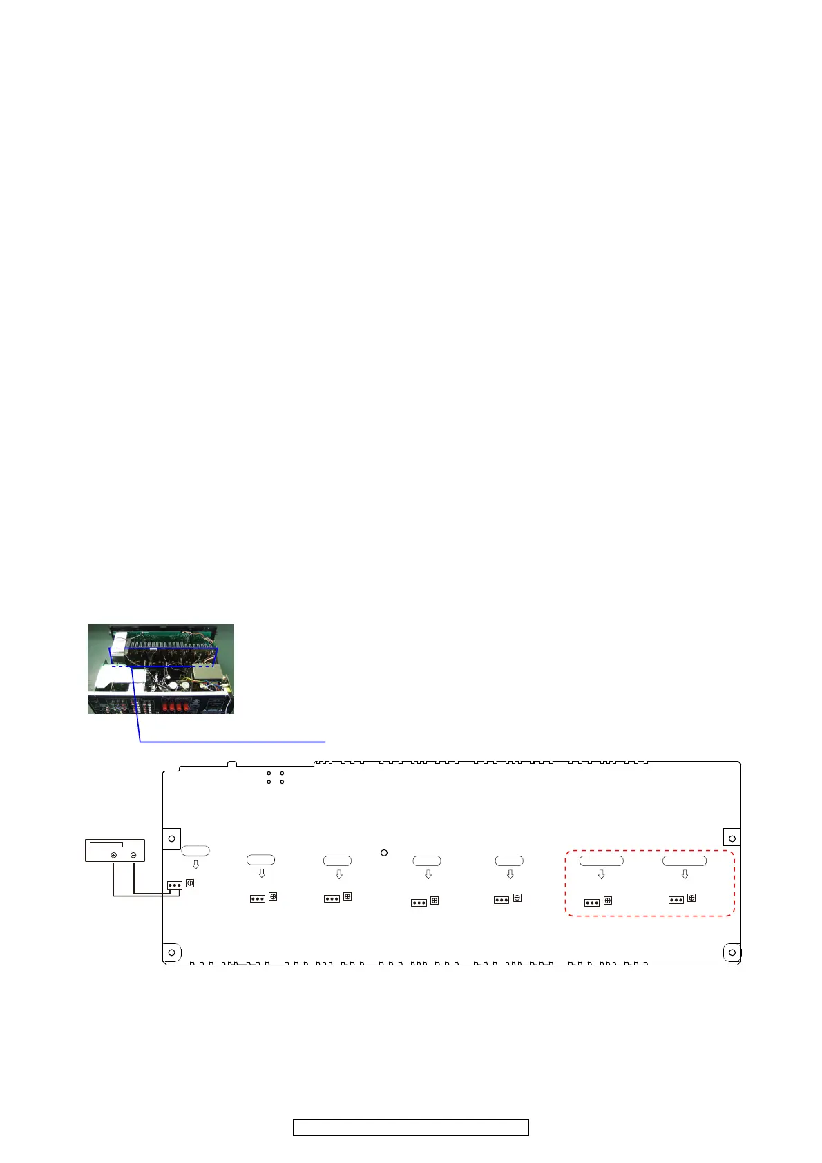
(1) Remove top cover and set VR1201 FL, FR, C, SL, SR, SBL, SBR on 7CH AMP UNIT at fully counterclockwise (c)
position(1910/790 model).
(1’) Remove top cover and set VR1201 FL, FR, C, SL, SR on 5CH AMP UNIT at fully counterclockwise (c) position(1610/
1620/590 model).
(2) Connect DC Voltmeter to test points (FRONT-Lch: TP1201, FRONT-Rch: TP1205, CENTER ch: TP1203, SUR-
ROUND-Lch: TP1202, SURROUND-Rch: TP1204, SURROUND-BACK Lch: TP1207(1910/790 model), SURROUND-
BACK Rch: TP1206 (1910/790 model)).
(3) Connect power cord to AC Line, and turn power switch "ON".
(4) Presetting.
MASTER VOLUME : "---" counterclockwise (c min.)
SPEAKER (Speaker terminal) : No load
(Do not connect speaker, dummy resistor, etc.)
MODE : 7CH STEREO (5CH STEREO)
FUNCTION : CD
(5) Within 2 minutes after the power on, turn VR1201 clockwise (x) to adjust the TEST POINT voltage to 1.5 mV ± 0.5 mV
DC.
(6) After 10 minutes from the preset above, turn VR1201 to set the voltage to 2.0 mV ± 0.5 mV DC.
(7) Adjust the Variable Resistors of other channels in the same way.
5CH AMP UNIT (1610/1620/590 model)
7CH AMP UNIT (1910/790 model)
7CH AMP UNIT (1910/790 model)
DC Voltmeter
F Lch
S Lch
C ch
S Rch
F Rch
S Back Lch
S Back Rch
T1201FL
T1201SL
V1201FL
V1201SL
T1201C
V1201C
T1201SR
V1201SR
T1201FR
V1201FR
T1201SBL
V1201SBL
T1201SBR
V1201SBR
 Loading...