40
AVR-1910/1620/1610/790/590
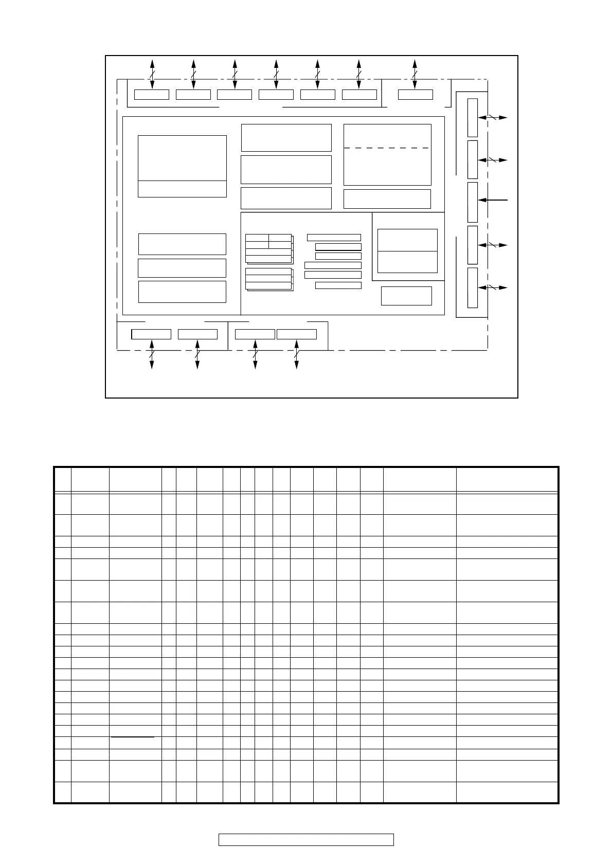
M30626FJPFP Block Diagram
M30626FJPFP Terminal Functio
n
PIN
No.
PIN PIN NAME I/O Type DET
Lv
Cnv
Op
(in)
Op
(ex)
Res
PURE
D
CEC
STBY
STBY
STOP
P. O F F
STOP
Function
1 P96/
(SOUT4)
NC O C - - - - Z - O/L O/L O/L UART
2 P95/
(CLK4)
MICDET I - Lv - - Eu Z - - O/L O/L Mic insert detect
3 P94 H/PDET I - Lv - - Eu Z - - O/L O/L Headphone insert detect
4 P93 FL_DATA O C - - - Z - O/L O/L O/L FLD control
5 P92/
SOUT3
MOSI O C - 5/3 - - Z - - O/L O/L Interface between Main CPU and
Sub CPU
6 P91/SIN3 SOMIm I - Lv 5/3 - - Z - - I O/L Interface between Main CPU and
Sub CPU
7 P90/CLK3 CLKMO O C - 5/3 - - Z - - O/L O/L Interface between Main CPU and
Sub CPU
8BYTEBYTE I---------- GND
9 CNVCS CNVSS I - - - - Ed Z - - I I Firmware update control
10 P87 FL_RST O C - - - Z - O/L O/L O/L FL display control
11 P86 REDLED O C - - - - Z - O/H O/H O/L H : ON Power indicator (red led) control
12 RESET RESET I - Lv - - Eu L - - I I RESET pulse input
13XOUTXOUT O---------- Oscillator connect
14VSS VSS ---- ------ GND
15XIN XIN I---------- Oscillator connect
16VCC VCC ----------- POWER 5V
17P85/NMINMI I---------- Connect to +5V
18 P84/INT2 PROTECTION
I-
E
↓
&
L
- - Eu Z - - I I Fall Edge & L PROTECTION Detect
19 P83/INT1 LED1 (TBD) O C - - - - Z - O/L O/L O/L H : ON LED control
20 P82/INT0 GRNLED O C - - - - Z - O/L O/L O/L H : ON Power indicator (green led)
control
21 P81 BLUE LED O C - - - - Z - O/L O/L O/L H : ON HD_AUDIO indicator (blue led)
control
Output (timer A): 5
Input (timer B): 6
Internal peripheral functions
Watchdog timer
(15 bits)
DMAC
(2 channels)
D-A converter
(8 bits X 2 channels)
Memory
ROM
(1)
RAM
(2)
A-D converter
(10 bits
X
8 channels
Expandable up to 26 channels)
UART or
clock synchronous serial I/O
(8 bits
X
3 channels)
System clock
generation circuit
XIN-XOUT
XCIN-XCOUT
PLL frequency synthesizer
Ring oscillator
M16C/60 series16-bit CPU core
Port P0
8
Port P1
8
Port P2
8 8 8 8
Port P6
8
8
R0LR0H
R1H R1L
R2
R3
A0
A1
FB
SB
ISP
USP
INTB
CRC arithmetic circuit (CCITT )
(Polynomial : X
16
+X
12
+X
5
+1)
Multiplier
7
8
8
0
1
Pt
r
oP
9
P
tro
P
5
_
8
P
tro
P
8
P
t
ro
P
7Pt
r
o
P
NOTES :
1. ROM size depends on microcomputer type.
2. RAM size depends on microcomputer type.
3. Ports P11 to P14 exist only in 128-pin version.
4. Use M16C/62PT on VCC1= VCC2.
Port P5
Port P4Port P3
Clock synchronous serial I/O
(8 bits
X
2 channels)
PC
FLG
Timer (16-bit)
Three-phase motor
control circuit
8 8 82
Port P11
Port P12
Port P14
Port P13
(3)
<VCC2 ports>
(4)
<VCC1 ports>
(4)
>
s
t
r
o
p1CC
V
<
)4(
<VCC2 ports>
(4)
<VCC1 ports>
(4)
(3) (3)
(3)
 Loading...