EasyManua.ls Logo

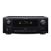
Denon AVR-2802 Service Manual

Denon AVR-2802
74 pages
To Next Page IconTo Next Page
To Previous Page IconTo Previous Page
Page #8 background image
AVR-2802/982
8
A/D SELECTOR
IC804
74LVX157
CODEC
D/A CONVERTER
IC801
AD1854
(2)256fs
(26)64fs
(25)fs
(27)DATA
INPUT
SELECTOR
IC505
151NS
COAXIAL
(15)
OPTICAL-1
OPTICAL-2
OPTICAL-3
(14)
(5)
(13)
OPTICAL
OUTPUT
(12)
IC506
151NS
(3)
(5)
(2)
(1)
IC800
LC89055W
CKOUT(13)
(5)DIN2
BCK
DATA
(14)
LRCK(15)
(16)
XIN(22)
XMCK(20)
12.288MHz
X801
MCLK
(44) (22) (25) (26)
SCLKN1 LRCKN1
SDATAN1
AUDATA0(41)
AUDATA1(40)
AUDATA2(39)
(30)CLKIN
IC814
CS493292
DSP
2
1
(27) (43) (42)
SCLK LRCLKCMPDAT
3
MCLK
DA SCK
DA LRCK
SD IN
256fs
64fs
fs
FRONT
SURROUND
256fs
64fs
fs
DATA
IC813
(7)
(13)
(10)
SN74LV4040APW
DIR
(6)SDTI1
IC602
AK4527
(7)SDTI2
(8)SDTI3
(39)MCLK
(4)BICK
(5)LRCK
(9)SDTO
XMT958 (3)
SURROUND BACK
CENTER/SW
SN74HC
SN74HC
* fs is a sampling frequency of input digital signal.
e.g.:sampling frequency 48kHz fs=48kHz
* 64fs and 256fs are 64 or 256 times the sampling frequency respectively.
e.g.: sampling frequency 48kHz
64fs: 48kHz x 64=3.072MHz
256fs: 48kHz x 256=12.288MHz
* The sampling frequency for analog input is fixed to 48kHz internally.
* (No.) indicates the pin number of individual.
* The arrow indicates the direction of signal as the input terminal pointed by
the arrow and the output terminal by the opposite.
Clock Flow
Table of Contents

Other manuals for Denon AVR-2802

Questions and Answers:

Denon AVR-2802 Specifications

General IconGeneral
Impedance8 ohms
Surround SoundDolby Digital, DTS, Dolby Pro Logic II
AM/FM TunerYes
Remote ControlYes
Number of Channels6.1
Frequency Response10 Hz - 100 kHz (+1, -3 dB)
Total Harmonic Distortion0.05%
Power Output90 W per channel (8 ohms, 20 Hz-20 kHz, 0.05% THD)
Video InputsComposite, S-Video
Video OutputsComposite, S-Video
Signal To Noise Ratio98 dB
Input Sensitivity200 mV
Input Impedance47 kOhms
Inputs8 Analog Audio (including Phono), 5 Digital Audio (3 Optical, 2 Coaxial)

Summary

SAFETY PRECAUTIONS

LEAKAGE CURRENT CHECK

Procedure to ensure unit safety before customer return.

SPECIFICATIONS

AUDIO SECTION

Detailed audio output and input specifications.

VIDEO SECTION

Specifications for video input/output levels and frequency response.

DISASSEMBLY

Top Cover Removal

Instructions for removing the top cover of the unit.

Front Panel Detachment

Steps to detach the front panel, including screw and hook removal.

BLOCK DIAGRAMS

SERVICING CAUTIONS

Initializing AV SURROUND RECEIVER

Procedure for initializing the receiver when µcom or DSP P.W.B. are replaced.

ADJUSTMENT PROCEDURES

Idling Current Adjustment

Procedure for adjusting idling current on the power unit using a DC voltmeter.

P.W.B. PARTS LIST

1U-3368 POWER UNIT ASS'Y

List of parts for the power unit P.W.B., including semiconductors and resistors.

1U-3369 EXT. IN UNIT ASS'Y

List of parts for the EXT. IN unit P.W.B., including semiconductors and connectors.

1U-3370 CONTROL UNIT ASS'Y

List of parts for the control unit P.W.B., including semiconductors and connectors.

1U-3371 REGULATOR UNIT ASS'Y

List of parts for the regulator unit, including semiconductors and resistors.

1U-3373 DSP/Video unit ass'y

List of parts for the DSP/Video unit P.W.B., including semiconductors and connectors.

SEMICONDUCTORS GROUP LIST

List of semiconductors for the unit, specifying part numbers and remarks.

RESISTORS GROUP LIST

Further listing of resistors with part numbers and associated remarks.

CAPACITORS GROUP LIST

Continuation of the detailed capacitor list, including part numbers and remarks.

OTHER PARTS GROUP LIST

List of miscellaneous parts such as connectors, beads, and semiconductors.

EXPLODED VIEW

Exploded View Diagram

Visual representation of unit components and their assembly order.

EXPLODED VIEW PARTS LIST

1U-3368 Power unit ass'y

List of parts associated with the power unit, referencing the exploded view.

1U-3369 EXT.IN unit ass'y

List of parts for the EXT.IN unit, referencing the exploded view.

1U-3370 Control unit ass'y

List of parts for the control unit, referencing the exploded view.

1U-3371 Regulator unit ass'y

List of parts for the regulator unit, referencing the exploded view.

1U-3373 DSP/Video unit ass'y

List of parts for the DSP/Video unit, referencing the exploded view.

WIRING DIAGRAM

SCHEMATIC DIAGRAMS (1/12)

SCHEMATIC DIAGRAMS (2/12)

SCHEMATIC DIAGRAMS (3/12)

SCHEMATIC DIAGRAMS (2/12) (continued)

SCHEMATIC DIAGRAMS (continued)

SCHEMATIC DIAGRAMS (3/12) (continued)

Related product manuals