EasyManua.ls Logo

Denon AVR-2803 Service Manual

Denon AVR-2803
113 pages
To Next Page IconTo Next Page
To Previous Page IconTo Previous Page
Page #7 background image
7
7
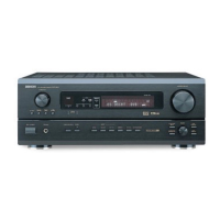
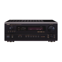
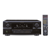
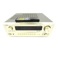
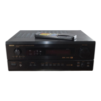
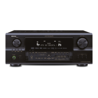
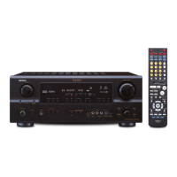
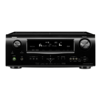
AVR-2803/983/AVC-2870
ADJUSTMENT
AudioSection
IdlingCurrent(1U-3469-1)
Requiredmeasurementequipment:DCVoltmeter
1. Preparation
(1)Avoiddirectblowfromanairconditioneroran
electricfan,andadjusttheunitatnormalroom
tempereture15 ℃〜30 ℃(59°F 〜86°F).
(2)Presetting
●POWER(Powersourseswitch)OFF
●SPEAKER(Speakerterminal)Noload
(Donotconnectspeaker,dummyresistor,etc.)
2. Adjustment
(1)RemovetopcoverandsetVR101,VR102,VR201,
VR301,VR302,VR401,VR402,on1U-3469-1
(PowerUnit)atfullycounterclockwise( ).
(2)ConnectDCVoltmetertotestpoints(FRONT-
Lch:TP301 ①② pin,FRONT-Rch:TP101 ⑤⑥ pin,
CENTERch:TP301 ③④ pin,SURROUND-Lch:TP101
pin,SURROUND-Rch:TP101 ①② pin,SURROUND
BACK-Lch:TP301 ⑦⑧ pin,SURROUNDBACK-Rch:
TP301 ⑤⑥ pin).
(3)ConnectpowercordtoACLine,andturnpower
switch"ON".
(4)Presetting.
MASTERVOLUME:"---"counterclockwise( min.)
MODE:7CHSTEREO
FUNCTION:CD
(5)Allow2minutes,andturnVR101clockwise( )to
adjusttheTESTPOINTvoltageto6.5mV ± 0.5mVDC.
(6)After10minutesfrompreset,turnVR101tosetthe
voltageto8mV ± 0.5mVDC.
(7)AdjusttheVariableResistorsofotherchannelsinthe
sameway.
(8)After5minutesfrom(6),turnVR101tosetthevoltage
to8mV ± 0.5mVDC.
(9)AdjusttheVariableResistorsofotherchannelsinthe
sameway.
調整
オーディオセクション
アイドリング電流の調整 (1U-3469-1)
調整に必要な測定器 : DCVoltmeter
1. 準備
(1)セットをクーラ、扇風機のそばなど風通しの良い場
所を避け、通常の使用状態に置きます。セットの周
囲温度は 15〜30 ℃、湿度は常湿とします。
(2)プリセット
●電源スイッチ OFF
●スピーカ端子無負荷
( スピーカ・ダミー抵抗器などを接続しない。)
2. 調整
(1)上カバーをはずし、1U-3469-1(パワーユニット)の
VR101,VR102,VR201,VR301,VR302,VR401,VR402
反時計方向 ( )に回し切った状態にセットします。
(2)テストポイント (FRONT-Lch:TP301 ①② pin,FRON-
TRch:
TP101 ⑤⑥ pin,CENTERch:TP301 ③④ pin,
SURROUND-Lch:TP101 ③④ pin,SURROUND-Rch:
TP101 ①② pin,SURROUNDBACK-Lch:TP301 ⑦⑧
pin,SURROUNDBACK-Rch:TP301 ⑤⑥ pin)に DC
Voltmeterを接続します。
(3)電源コードを AC100V(95〜105Vの範囲でも可)に
接続し、電源スイッチを "ON"にします。
(4)ON後、次のようにセットします。
●MASTERVOLUME(音量調節つまみ)→反時計方向
( )に回す、最小の状態にする。
●SPEAKER(スピーカ端子)→無負荷(スピーカ、ダ
ミー抵抗器などを接続しない。
MODE:7CHSTEREO 
FUNCTION:CD
(5)2分以内に VR101を時計方向 ( ) に回しテストポ
イントの電圧を次のように調整します。
6.5mV ±0.5mVDC
(6)予備調整から 10分後 VR101を回し、次のように電圧
を設定します。
8mV± 0.5mVDC
(7)同じ方法で各チャネルの可変抵抗を調整します。
(8)(6) 項設定から 5分後 VR101を回し、次のように電圧
を設定します。
8mV± 0.5mVDC
(9)同じ方法で各チャネルの可変抵抗を調整します。

Table of Contents

Other manuals for Denon AVR-2803

Questions and Answers:

Denon AVR-2803 Specifications

General IconGeneral
Power Output90 W per channel (8 ohms, 20 Hz - 20 kHz, 0.05% THD)
Channels7.1
Dolby SupportDolby Digital, Dolby Pro Logic II
Digital Inputs2 coaxial, 3 optical
Weight14.5 kg
TypeAV Receiver
Output Power per Channel90 W (8 ohms, 20 Hz - 20 kHz, 0.05% THD)
Frequency Response10 Hz - 100 kHz (+1, -3 dB)
Input Sensitivity200 mV
Input Impedance47 kOhms
Total Harmonic Distortion0.05%
Input Sensitivity/Impedance200 mV / 47 kOhms
Tuner Frequency RangeFM: 87.5 - 108 MHz, AM: 522 - 1611 kHz
DTS SupportDTS, DTS-ES, DTS Neo:6
OutputsComposite: 2, Component: 1
Video outputsComposite: 2

Summary

Safety Precautions

Leakage Current Check

Check for customer safety before returning the unit, ensuring proper electrical insulation.

Disassembly Procedures

Power/Control Unit Check

Method for checking the power and control unit while the unit is powered on.

Servicing Cautions and Initialization

AV Receiver Initialization

Procedure to initialize the AV SURROUND RECEIVER, typically after component replacement.

Adjustment Procedures

Audio Section Idling Current Adjustment

Procedure for adjusting the idling current in the audio section.

System Diagrams

Wiring Diagram

Overall wiring diagram showing connections between different units and components.

Schematic Diagrams (Parts 1-12)

Detailed schematic diagrams for various receiver units, presented in 12 parts.

Schematic Diagrams (Japan Models)

Detailed schematic diagrams for units specific to Japan models.

Test Mode Operations

μcom/DSP Error Display Mode

Procedure to check for and display microcomputer or DSP errors using a specific test mode.

Printed Wiring Board Layouts

Parts List Conventions

Parts List Notation

Explains symbols and notation used in the parts list for resistors, capacitors, and units.

Parts List by Unit (Except Japan)

1U-3469 Power Unit Parts

List of semiconductor and resistor parts for the 1U-3469 POWER UNIT (Except Japan model).

Parts List by Unit (For Japan)

Exploded View and Parts List

Exploded View of Components

Visual representation of the unit's components and their assembly order.

Exploded View Parts List

Detailed list of all parts referenced in the exploded view, categorized by unit.

Related product manuals