Explanatory Photos for DISASSEMBLY
• Fortheshootingdirectionofeachphotosusedinthismanual,seethephotobelow.
• A, B, C and Dinthephotobelowindicatetheshootingdirectionsofphotos.
• Thephotographswithnoshootingdirectionindicatedweretakenfromthetopoftheunit.
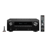
• PhotosofAVR-S950HE3areusedinthismanual.
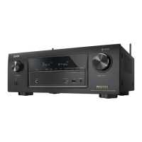
The viewpoint of each photograph
(Shootingdirection:X)[Viewfromthetop]
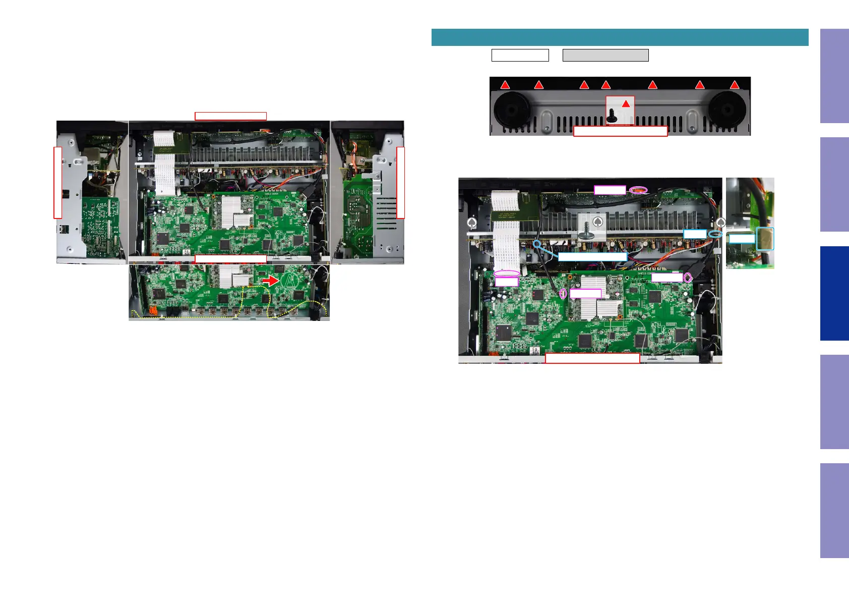
Attention:
WhenreinsertingtheAntennaCableafterithasbeendisconnected,makesureitisfacingthedirection
shownin
Ⓐ
above.
↓Shooting direction: C↓
↑Shooting direction: D↑
↑Shooting direction: A↑
↓Shooting direction: B↓
�
Proceeding : TOP COVER → FRONT PANEL ASSY
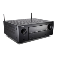
(1) Removethescrews.
(2) Removethescrews.Cutthewireclamp,thenremovetheCORDHOLDERandconnector.
RemovetheTAPE.RemovetheFFC.
1. FRONT PANEL ASSY
View from the bottom
x7
↑Shooting direction: A↑
x2
CP4400
FFC
N1008
N1000
CORD HOLDER
CUT
TAPE
Before Servicing
This Unit
Electrical Mechanical Repair Information Updating
69
 Loading...