4
EN
Specifications Elite Control
Additional Parts
1
DX CW
Required for CW Installations (not included)
Water Inlet Temperature Sensor X
Optional Parts
Outside Air Temperature (OAT) Sensor X X
Inside Air Temperature Sensor X X
Auxiliary Electric Heater
2
X X
Room Temperature/Relative Humidity
Combination Sensor
2
X X
Seawater Low-Limit Temperature Sensor
2
X
Pump Sentry Water Sensor X
1
Additional parts are not included with the standard control package.
2
Available in soware revision C39 and newer.
I
The maximum length for the display and sensor
cables is 75 (22.9 m).
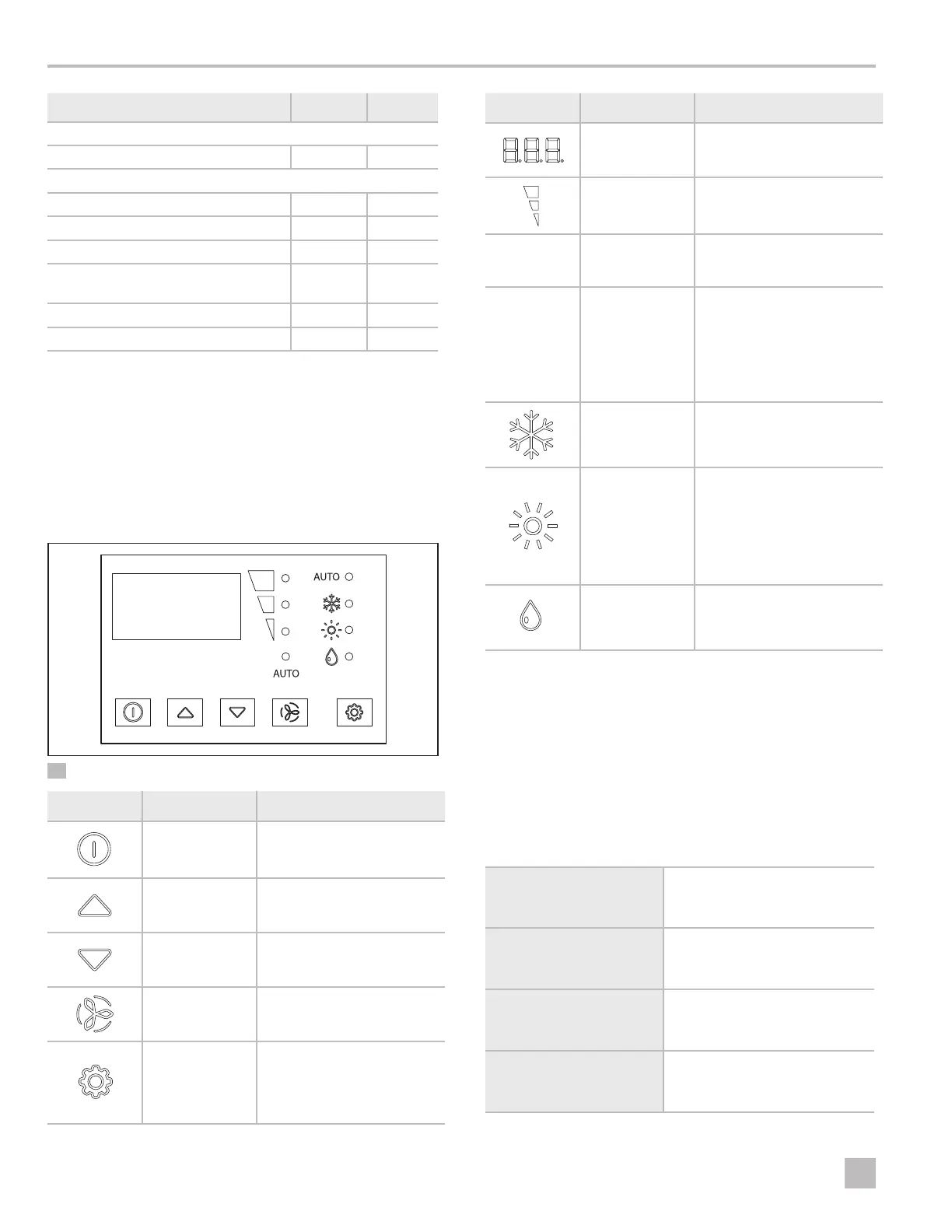
3.2 Display Features
This section explains the function of the buttons and
indicators on the Elite Control display.
1 Elite Control Display
Button Button Name Function
Power
Toggles between ON and OFF
mode
Up
Raises the temperature set
point by 1 °F (0.6 °C)
Down
Lowers the temperature set
point by 1 °F (0.6 °C)
Fan
Cycles through the different
fan speeds
Mode
Selects one of the
four operating modes
(AUTOMATIC, COOL, HEAT,
or DEHUMIDIFICATION) when
the system is in the ON mode
Indicator Indicator Name Function
Temperature LED
Display
Displays the inside, set
point, outside, and water
temperatures
Fan Speed
Indicates the fan speed as
high, medium, or low
AUTO
Automatic Fan
Mode
Located below the fan speed
indicator, the LED illuminates
when active
AUTO
Automatic Mode
Located above the COOL
mode indicator, the LED
illuminates when active.
• The COOL or HEAT mode
LED also lluminates to
indicate which cycle is
active
Cool Mode
When only this indicator is lit, it
indicates the COOL-only mode
is active
Heat Mode
• When only this indicator is
lit, it indicates the HEAT-
only mode is active
• When the indicator is
flashing, indicates the
AUXILIARY HEAT mode is
active
1
Dehumidification
Mode
Indicates DEHUMIDIFICATION
mode is active
1
If parameter P-13 for the auxiliary heat is enabled, it can also be selected and the
display will show A-H.
4 Specifications
The following table lists the Elite Control dimensions,
cables, system inputs, and operational specifications.
4.1 Product Dimensions
Display Panel Dimensions
for the Idea Bezel
4.4 in. x 3.0 in.
(112 mm x 76 mm)
Display Panel Dimensions
for the Eikon Bezel
4.5 in. x 2.9 in.
(114 mm x 74 mm)
Cut-Out Dimensions for
the Idea Bezel
2.3 in. x 3.5 in.
(58 mm x 89 mm)
Cut-Out Dimensions for
the Eikon Bezel
1.9 in. x 2.8 in.
(48 mm x 71 mm)

 Loading...