8
EN
Installation Elite Control
6 Installation
WARNING: ELECTRIC SHOCK HAZARD.
Turn power OFF before performing any electrical
installation or maintenance activities. Failure to
obey this warning could result in death or serious
injury.
NOTICE: Failure to obey the following notices could
result in damage to the product:
• Do not locate the display panel in direct sunlight,
near any heat-producing appliances, or in a bulkhead
where temperatures radiating from behind the panel
may affect performance.
• Do not mount the display in the supply-air stream or
above or below a supply-air or return-air grille.
• Do not mount the display behind a door, in a corner,
under a stairwell, or any place where there is no freely
circulating air.
• Do not staple sensor cables during installation.
• Do not use a screw gun and do not over-tighten the
screws when mounting the display. Either method
may damage the display.
I
The system’s display built-in temperature sensor
is located in the control’s display panel. An
optional inside air temperature sensor is required if
installing the display panel in a cabinet, enclosed
space, or any area where the accurate sensing of
the room temperature would be impaired.
This section describes how to install an Elite Control.
6.1 Choosing a Display Panel
Location
Place the display panel in an area that meets the
following location criteria:
• Mounted on an inside wall of the cabin, away from
direct sunlight
• Sets slightly higher than mid-height of the cabin
• Located in an area of freely circulating air
• Placed a maximum distance of 15 (4.6 m) from the
air conditioner
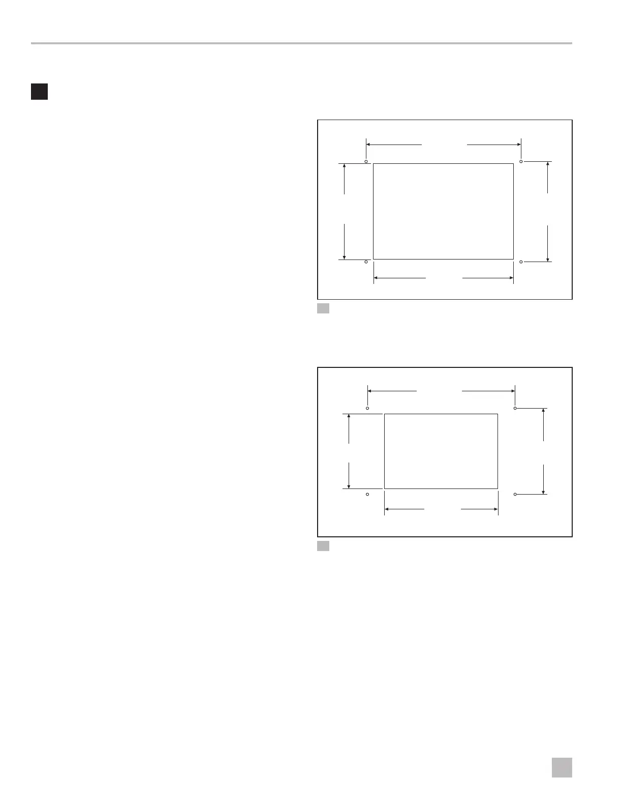
6.2 Preparing the Wall
Cut the cabin wall to fit the display panel, according to
the bezel being used.
q
w
e
r
4 Idea Bezel Cutout Dimensions
q
2.3 in. (58 mm)
e
2.4 in. (61 mm)
w
3.8 in. (97 mm)
r
3.5 in. (89 mm)
q
w
e
r
5 Eikon Bezel Cutout Dimensions
q
1.9 in. (48 mm)
e
2.2 in. (56 mm)
w
3.8 in. (97 mm)
r
2.8 in. (71 mm)
6.3 Installing an Optional Sensor
1. Mount the optional sensor according to the
installation instructions included with the sensor.
2. Plug the sensor cable into the appropriate sensor
jack on the upper side of the control board. Refer to
“Wiring Diagrams” on page 6 for details on the
sensor jack locations.

 Loading...