6
EN
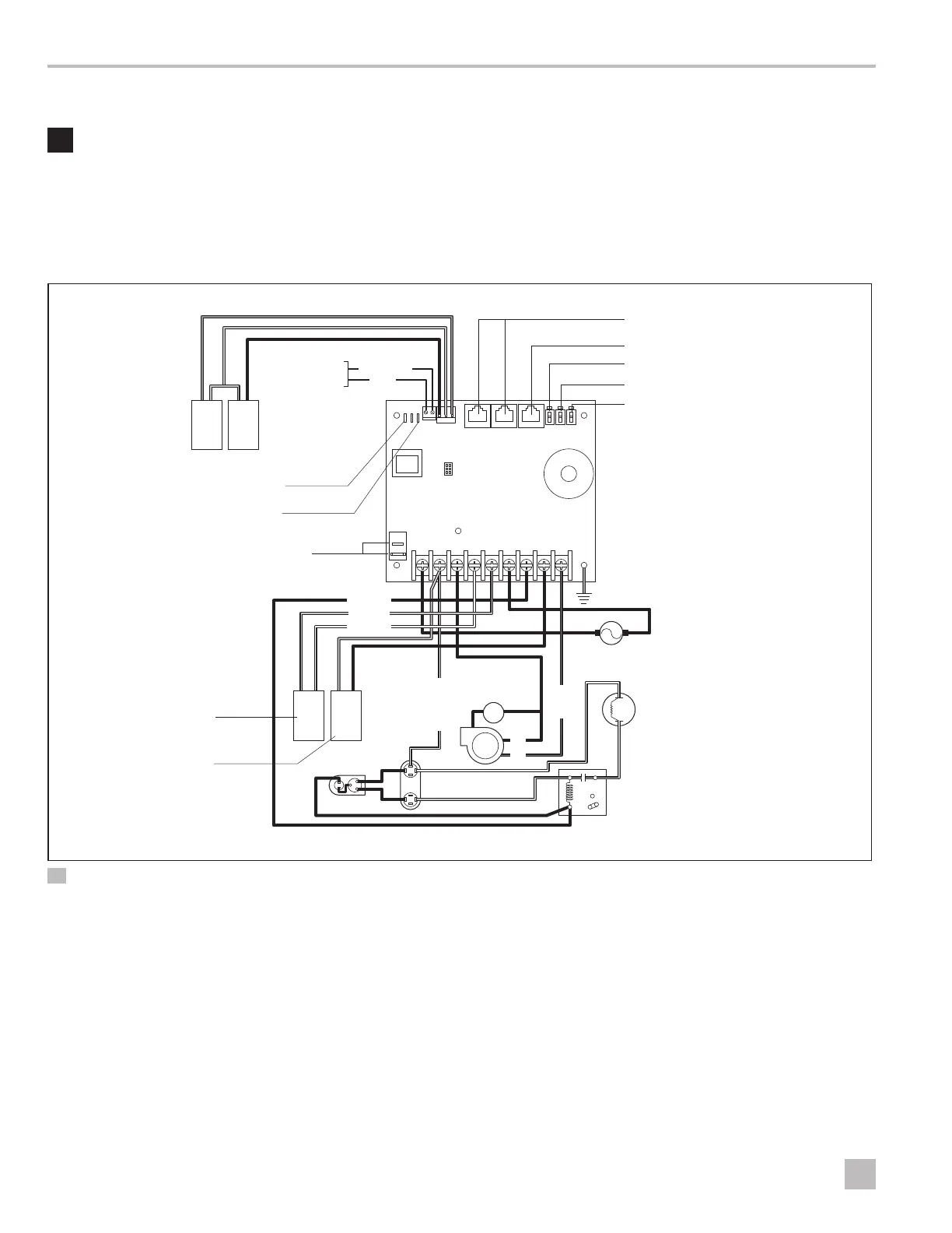
Wiring Diagrams Elite Control
5 Wiring Diagrams
WARNING: ELECTRIC SHOCK HAZARD.
Turn power OFF before performing any electrical
installation or maintenance activities. Failure to obey
this warning could result in death or serious injury.
Figure 2 and Figure 3 provide examples of the DX and
CW Wiring for the Elite Control.
JP5 Temperature Sensor Selection Jumper
JP2 Low Pressure Switch Jumper
Run Capacitor
Low-Pressure
Switch
High-Pressure
Switch
Optional
DC Blower
Comp L1
Pump L1
Pump L2
0-10 VDC
GND
Fan L1
Comp L2
Compressor
Display Jacks (for 8- or 6-pin display and cables)
Inside Temperature Sensor Jack
Not Active
Optional Water-Out Temperature Sensor
Optional Outside Air Temperature Sensor
Ground
Start
Capacitor
Start Relay
1
6
4
5
2
L2
AC
Fan
Fan Run
Capacitor
L1
L1
L2
Pump or
Pump Relay Panel
Gate Terminals to
Auxiliary Heat Relay
Reversing Valve or
Electric Heat
2 DX Wiring Diagram

 Loading...