19
Connections
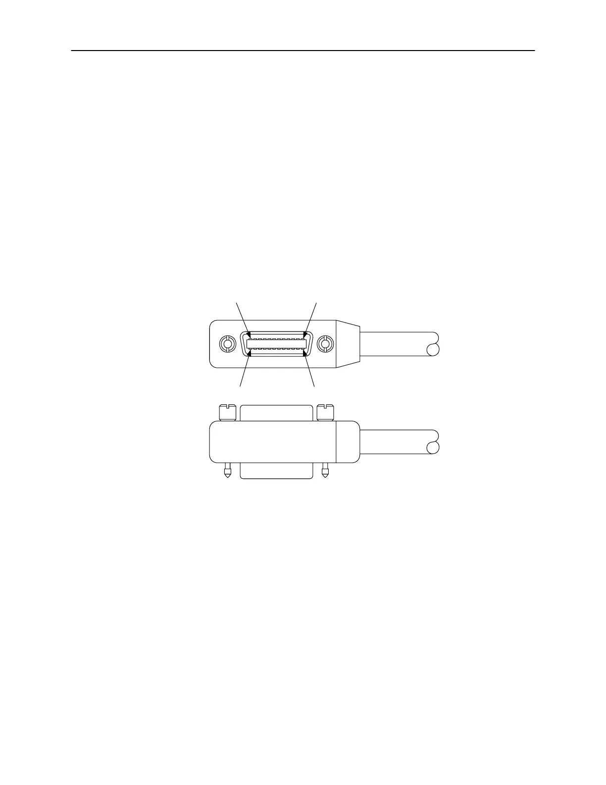
3.5 GPIB Control Connection
On the rear panel of the matrix is a GPIB (IEEE-488) control port which gets
connected to the GPIB port of a computer (controller) using a shielded IEEE-
488 interface cable with metric mounting screws. Figure 3-4 shows the
connector configuration and Table 3-4 shows the signal assignments.
3.5.1 GPIB Control Connector
You can link devices in either a linear, star or combination configuration using a
shielded 24-conductor cable. The standard IEEE-488 cable has both a plug
and receptacle connector on both ends. This connector is the Amphenol
CHAMP or Cinch Series 57 MICRO RIBBON type. See figure 3-4.
Figure 3-4 GPIB Control Connector
12 1
24
13
The following restrictions apply for normal operation when attaching instruments
to the GPIB:
• A maximum separation of 4 meters between any two instruments and an
average separation of 2 meters over the entire bus.
• A maximum total cable length of 20 meters.
• No more than 15 devices on the bus, with no less than two-thirds
powered on.
• No two instruments having the same address.
If you are unable to meet the above restrictions, the use of bus extenders is
recommended.
 Loading...